
Wireless control device

a control device and wireless technology, applied in the direction of instruments, cathode-ray tube indicators, electrophonic musical instruments, etc., can solve the problems of slow response, inconvenient operation, and general well-adapted keyboards for long periods of operation by human users

Inactive Publication Date: 2004-06-08
HARMONIC RES
View PDF13 Cites 299 Cited by
  • Summary
  • Abstract
  • Description
  • Claims
  • Application Information

AI Technical Summary

Benefits of technology

Enables comfortable and precise control of pointing applications without the need for broad hand motions, supports gesture recognition for character, word, and phrase-level data entry, and is suitable for use in sterile and combustible environments, reducing the risk of injury and improving usability across various activities.

Problems solved by technology

However, keyboards are not generally well-adapted for long periods of operation by a human user and alternative arrangements such as those alluded to above generally involve some degree of inconvenience, slow response, substantial user training and accommodation and / or significant data processing resources.
However, even this related device, like other existing devices, is inherently limited in its capabilities.
This can become extremely uncomfortable and tiring to the user.
Furthermore, it does not provide the fine sense of cursor control that one would attain by using a conventional computer mouse.
Additionally, existing devices are generally limited to character-level data entry, and this data entry is extremely sensitive to hand orientation.
This further restricts the usefulness of existing devices.

Method used


Image

  • Wireless control device
  • Wireless control device
  • Wireless control device

Examples


Embodiment Construction

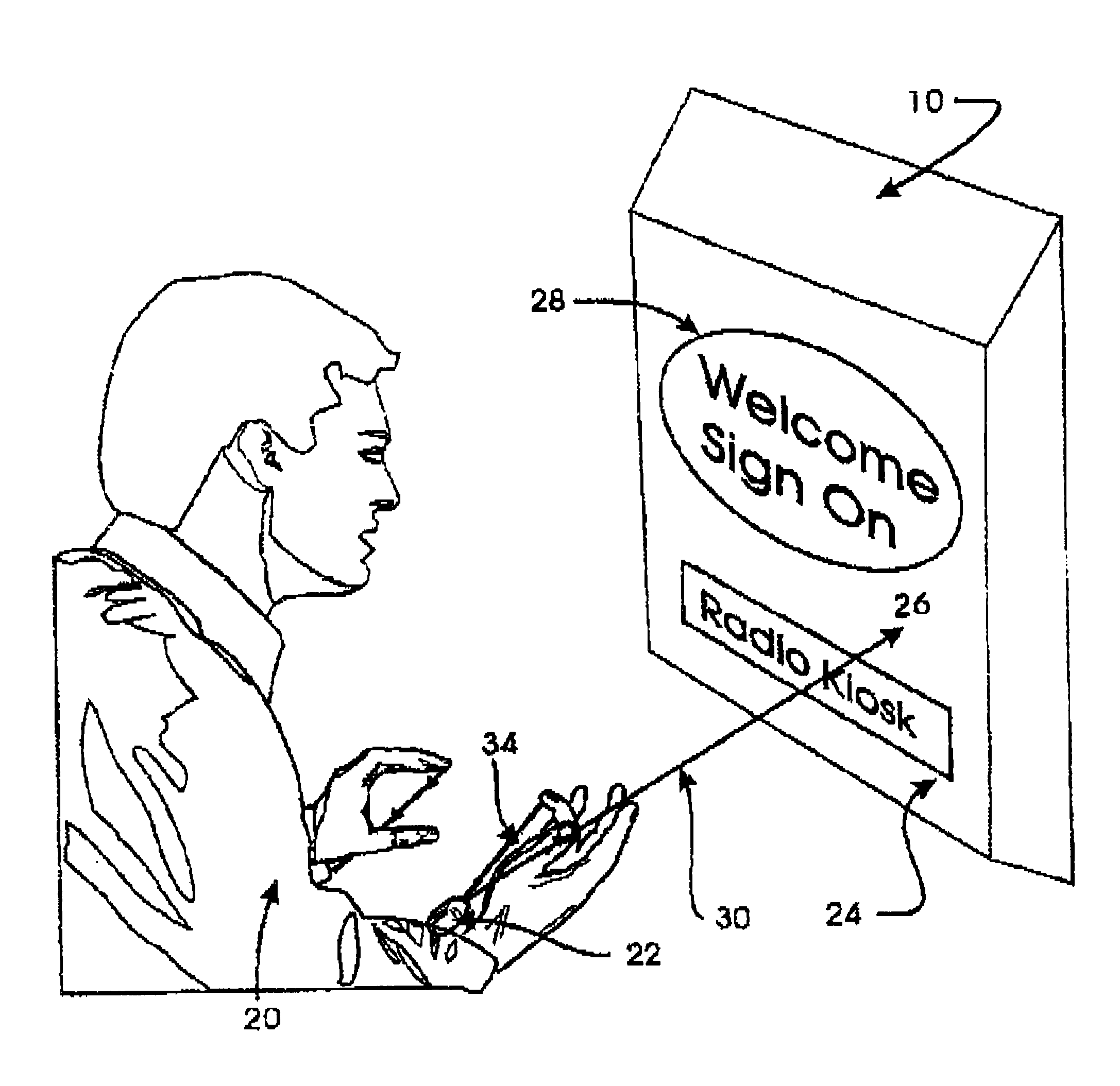
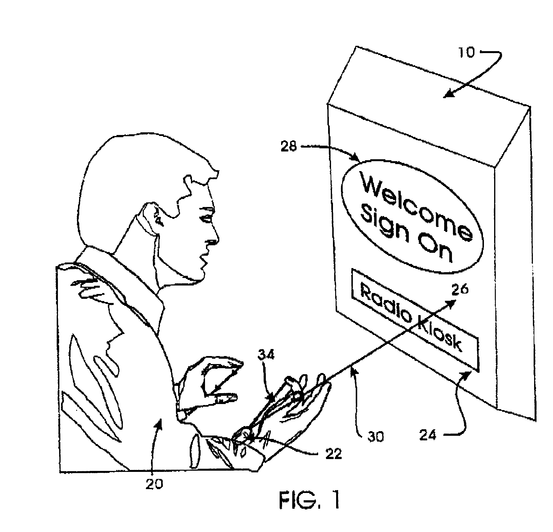
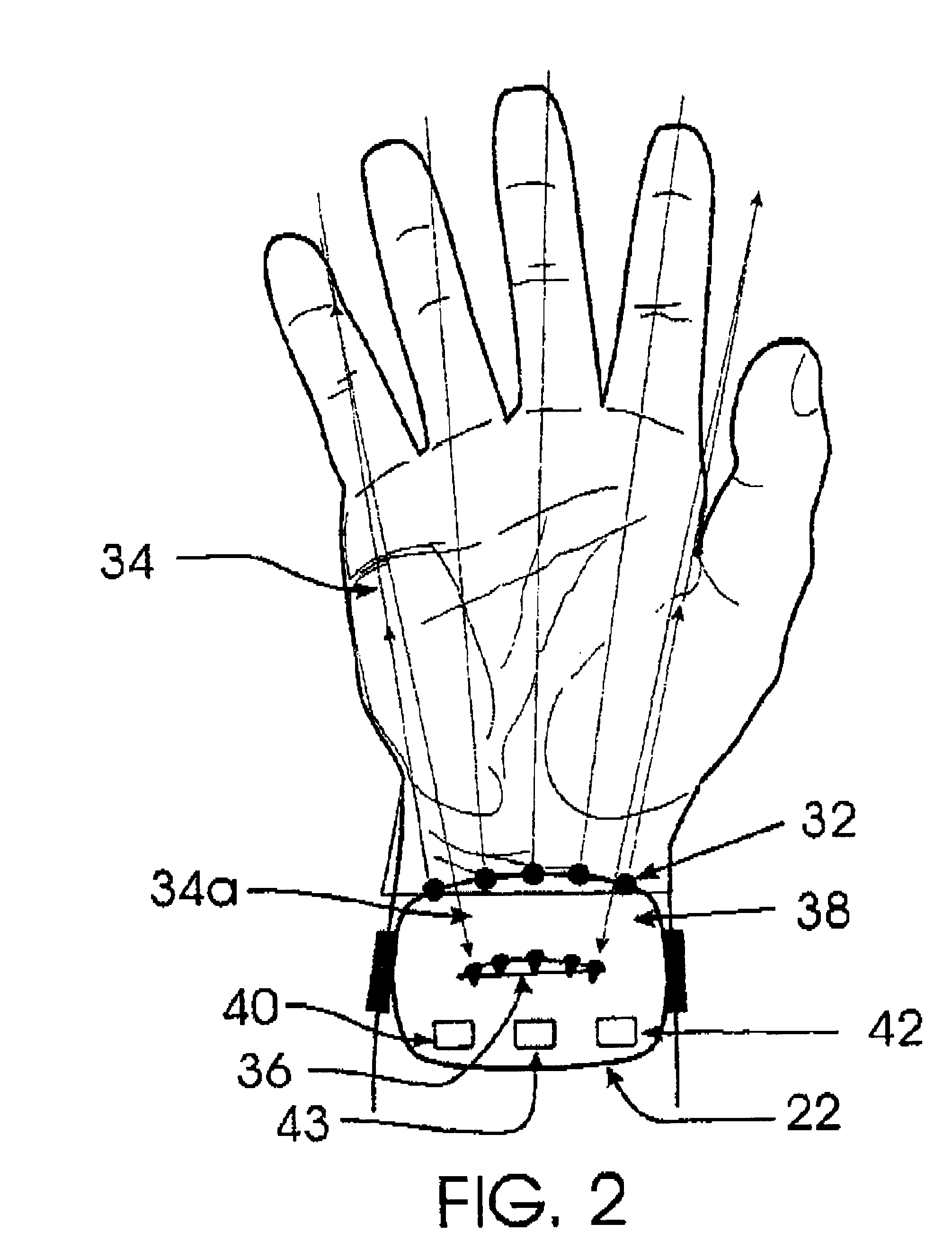
Referring now to the drawings, and more particularly to FIGS. 1 and 2, there is shown an exemplary and generalized application of the improved wireless control device 10. An operator 20 wears a small, lightweight housing 22 on at least one wrist or other convenient location on the body. The wrist is preferred as being proximate to the fingers which would ordinarily be used to operate a keyboard. However the invention may be adapted freely in accordance with its basic principles of operation as desired to accommodate the operator as a manner of convenience, physical handicap, or the like. A controlled device 24 is provided and includes a sensor 26 for light or any other form of energy suitable for transmission of a coded signal. Controlled device 24, hereinafter referred to as a base station for generality, preferably also includes a transducer 28, such as a display or an audio annunciator such as a beeper or speech synthesizer, to confirm receipt of a coded signal 30 and recognition...


PUM


Abstract

A wireless control device includes a small, lightweight housing worn by an operator, for example on the operator's wrist, and a controlled device, for example a personal computer. Several optical emitters, preferably light emitting diodes operating in the infrared range, and several optical detectors are provided on the housing. At least one x-axis emitter-detector pair operates to detect an x-direction of a pointing motion or gesture, and at least one y-axis emitter-detector pair operates to detect a y-direction of a pointing motion or gesture. This motion can then be used to cause a response in the controlled device. For example, angles of the operator's hand at the wrist can be interpreted to induce motion of a cursor on a computer display. The device may also include a motion sensor, an environmental condition sensor, or a voice recognition sensor, and can also be adapted for gesture recognition and image scanning applications.

Description

1. Field of the InventionThe present invention generally relates to portable selective data capture and selective control devices providing an interface between a user and a controlled device and, more particularly, to arrangements for providing data or control input to devices such as a data processor, musical instrument, communication device or the like while allowing freedom of movement and minimal interference with other activities for a user.2. Background DescriptionMost mechanical and electrical devices capable of multiple functions require and provide for user control for selection between those functions and initiation and termination of the function selected. In general, multiple buttons in the nature of a keypad or keyboard of arbitrary extent has been the arrangement of choice for communicating user selection and / or control to the device. In recent years, other arrangements such as pointing devices and voice-responsive systems have come into relatively widespread use. Fur...

Claims


Application Information

Patent Timeline
Patent Type & Authority Patents(United States)
IPC IPC(8): G06F3/033G06F3/02G06F3/00G10H1/00G09G1/00G06F3/01G06F3/0346G06F3/038G06F3/042
CPCG06F3/014G06F3/017G06F3/0202G06F3/0421G06F3/0423G10H1/0008G10H2220/201G10H2220/221G10H2220/321G10H2220/405G10H2240/211G06F3/03
Inventor HOWARD, ROBERT BRUCE
Owner HARMONIC RES
Learn More