
Method of refreshing an electrically erasable and programmable non-volatile memory

a non-volatile memory, electrically erased technology, applied in static storage, digital storage, instruments, etc., can solve the problems of data retention, loss of electric charge stored, and particular acute problems of modern flash memory

Inactive Publication Date: 2004-05-04
STMICROELECTRONICS SRL +1
View PDF4 Cites 110 Cited by
  • Summary
  • Abstract
  • Description
  • Claims
  • Application Information

AI Technical Summary

Benefits of technology

The present invention relates to a method of refreshing an electrically erasable and programmable non-volatile memory, which is commonly used in various applications such as PCs, cellular phones, automotive devices, digital still cameras, and the like. The method involves verifying whether a memory cell has drifted from a correct condition and restoring the correct condition if the drift is positive. This helps to prevent data loss and ensures that the memory can be used again even if there is a power supply cut during the refreshing procedure. The invention also provides a corresponding electrically erasable and programmable non-volatile memory.

Problems solved by technology

Data retention is one of the most important problems of the flash memories.
In fact, the transistors are subjected to different electric stresses during operation of the flash memory; these stresses may cause injection of electric charge into their floating gates (with an undesired programming of the transistors), or they may cause loss of the electric charge stored therein (with an undesired erasure of the transistors).
This problem is particular acute in modern flash memories, which feature a very thin oxide layer.
The refreshing procedures known in the art require the steps of copying a sector of the flash memory onto a volatile memory, erasing the whole sector, and then restoring the data from the volatile memory; therefore, any power supply cut during the refreshing procedure may cause a loss of data stored in the volatile memory and then the impossibility of restoring the data onto the flash memory.
However, none of the solutions proposed in the prior art in any way addresses the data retention problem described in the foregoing.

Method used


Image

  • Method of refreshing an electrically erasable and programmable non-volatile memory
  • Method of refreshing an electrically erasable and programmable non-volatile memory
  • Method of refreshing an electrically erasable and programmable non-volatile memory

Examples


Embodiment Construction

It should be understood that these embodiments are only examples of the many advantageous uses of the innovative teachings herein. In general, statements made in the specification of the present application do not necessarily limit any of the various claimed inventions. Moreover, some statements may apply to some inventive features but not to others. In general, unless otherwise indicated, singular elements may be in the plural and vice versa with no loss of generality. In the drawing like numerals refer to like parts through several views.

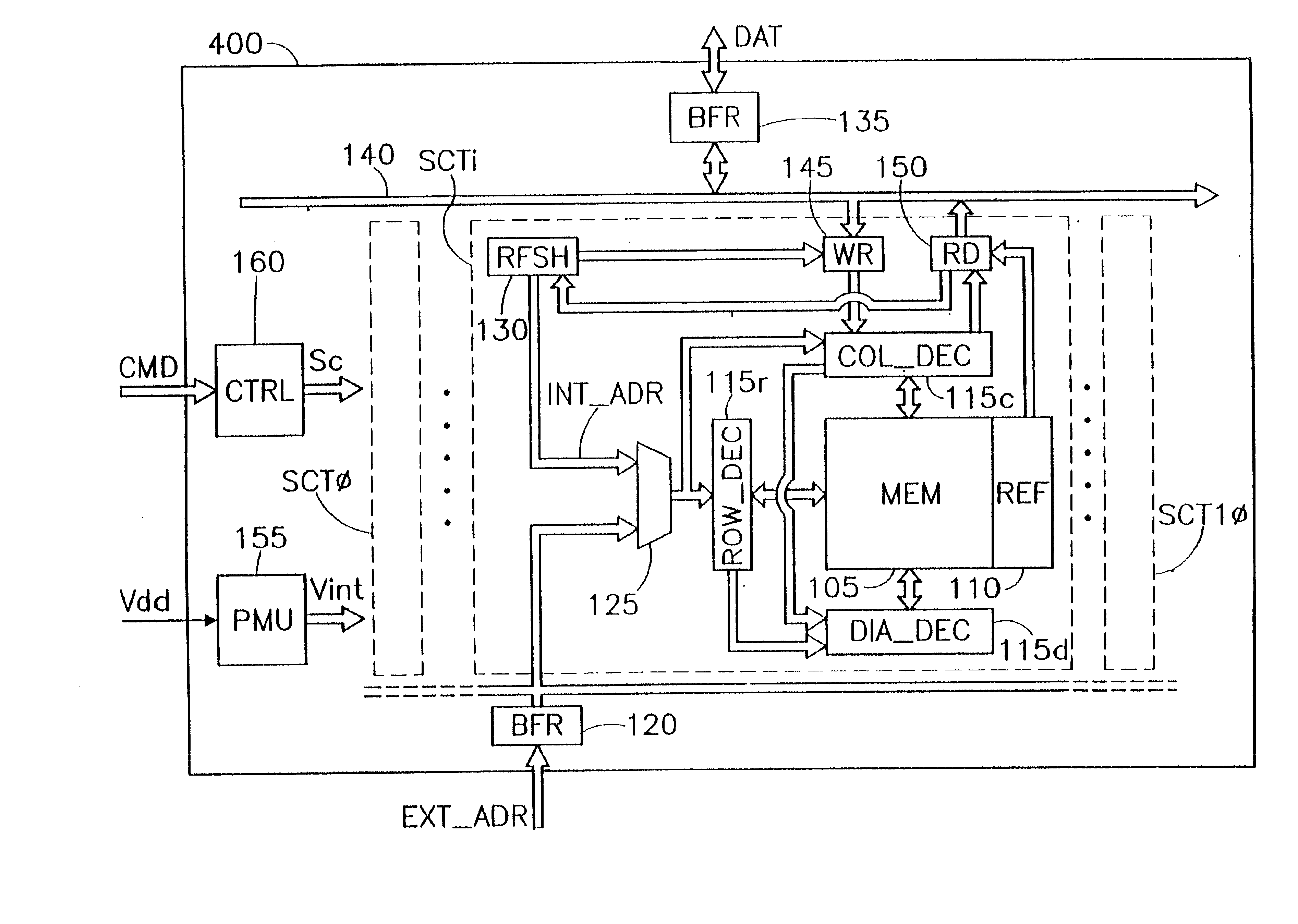
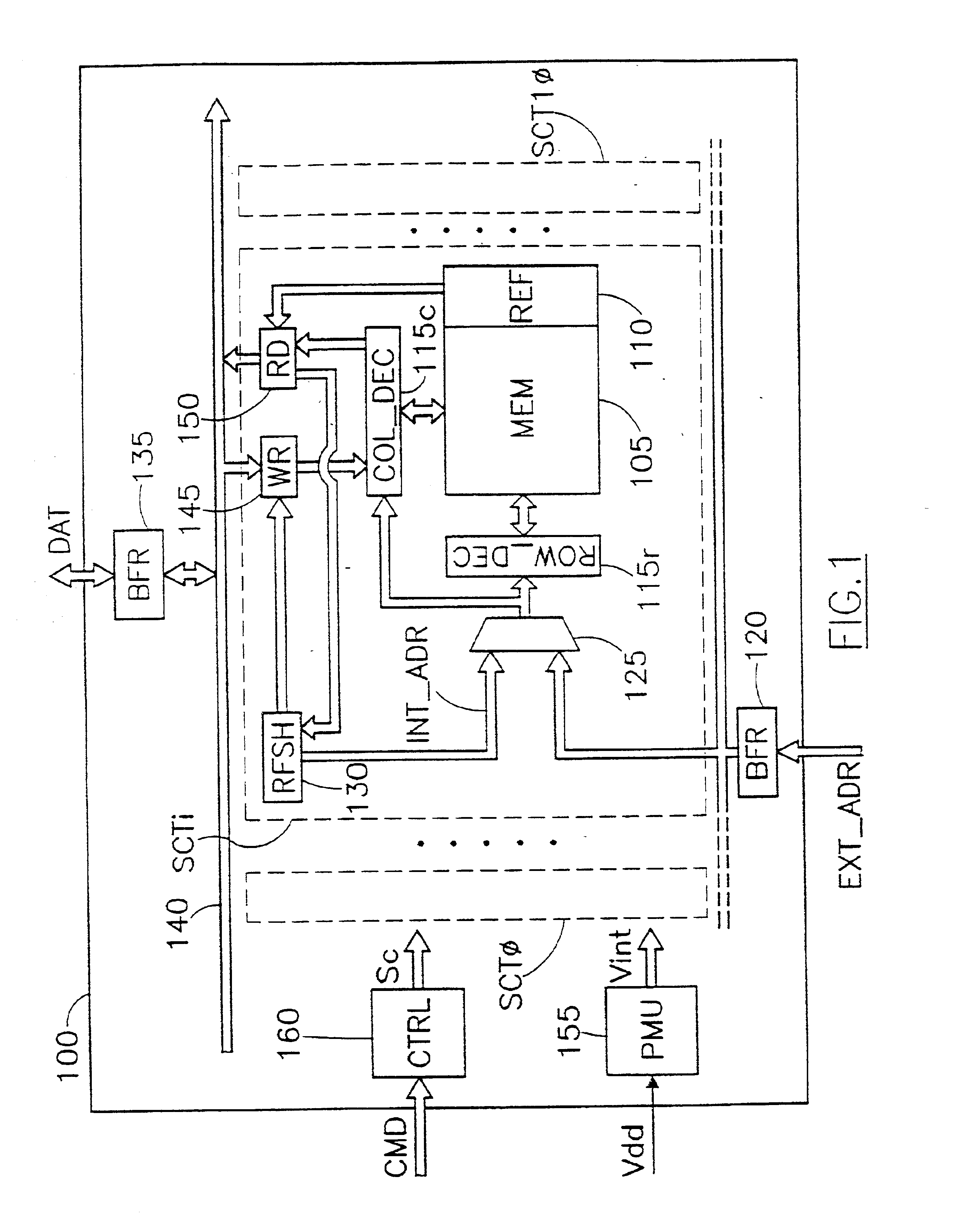
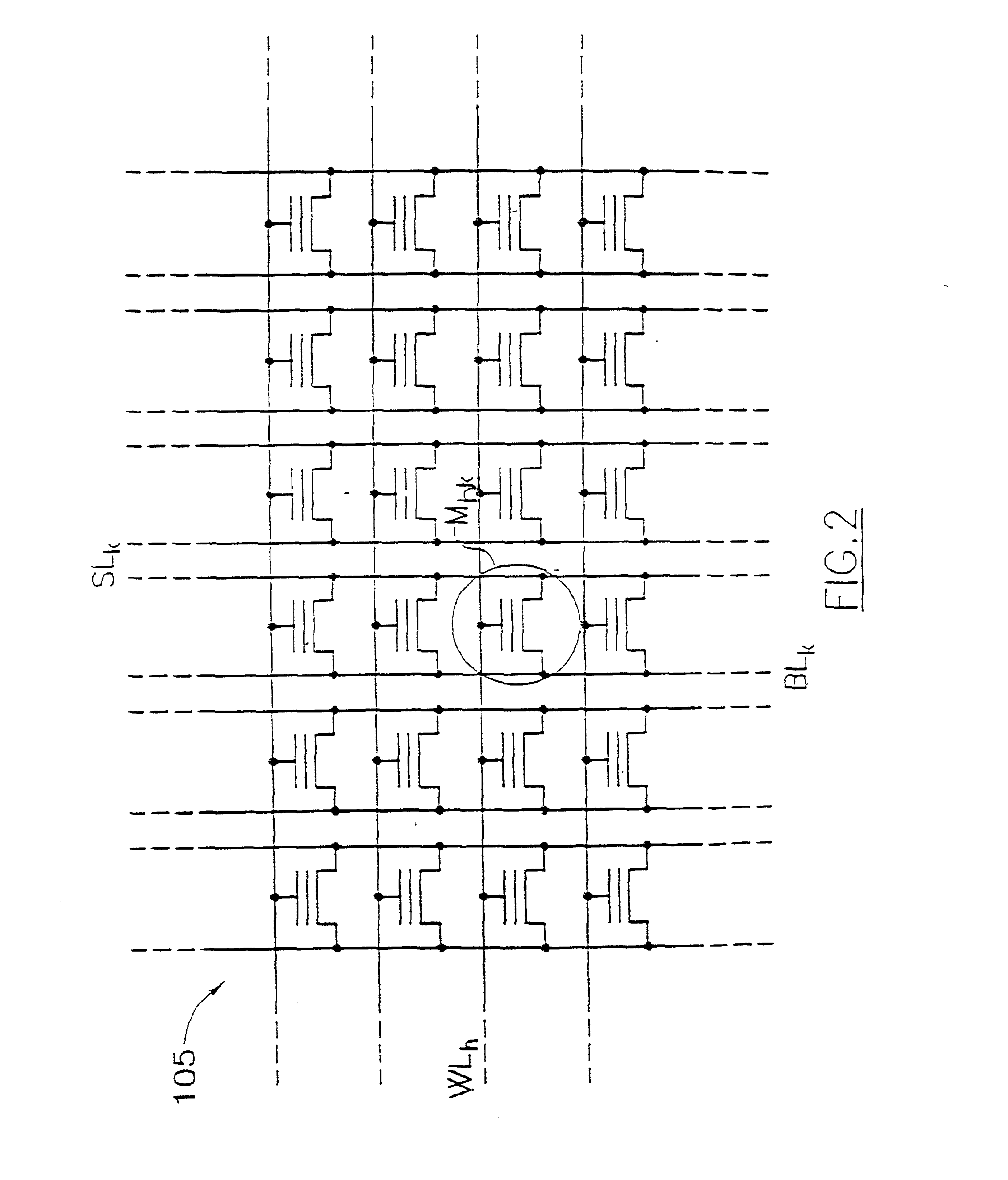
With reference in particular to FIG. 1, a flash memory 100 is shown. The flash memory 100 is segmented into a plurality of sectors SCTi (for example, eleven sectors with i=0 . . . 10); a generic sector SCTi includes a matrix (MEM) 105 of memory cells, with a respective array (REF) 110 of reference cells. Typically, the flash memory 100 has an asymmetric architecture, wherein a first sector has a reduced capacity in comparison with the other sector...


PUM


Abstract

A method (1110a;1110b) of refreshing an electrically erasable and programmable non-volatile memory (100) having a plurality of memory cells (Mhk) is proposed. The method includes the steps of: verifying (1106-1114; 1152-1162) whether a memory cell has drifted from a correct condition (i.e., a predetermined voltage and / or voltage range), and individually restoring (1116-1130) the correct condition of the memory cell if the result of the verification is positive.

Description

This application is based upon and claims priority from prior European Application No. 01830418.8, filed Jun. 21, 2001, the disclosure of which is hereby incorporated by reference in its entirety.1. Field of the InventionThe present invention relates to a method of refreshing an electrically erasable and programmable non-volatile memory.2. Description of Related ArtNon-volatile memories, which can be erased and programmed electrically, are commonly used in several applications when the data stored in the memory must be preserved even if a power supply is off. For example, a flash memory is a particular type of E.sup.2 PROM, wherein each memory cell consists of a single transistor (typically a floating gate MOS transistor). The transistors of the flash memory are programmed by injecting an electric charge into their floating gates. Conversely, the transistors are erased by discharging their floating gates; generally, the flash memory is erased in blocks (or sectors) formed by a few t...

Claims


Application Information

Patent Timeline
Patent Type & Authority Patents(United States)
IPC IPC(8): G11C16/34G11C16/06
CPCG11C16/3418G11C16/3431
Inventor BERETTA, FRANCO ENRICO
Owner STMICROELECTRONICS SRL
Learn More