
Electrically heated surgical cutting instrument

Inactive Publication Date: 2004-04-27
THERMAL SCALPEL
View PDF34 Cites 95 Cited by
  • Summary
  • Abstract
  • Description
  • Claims
  • Application Information

AI Technical Summary

Benefits of technology

Accordingly, the present invention provides a surgical cutting instrument having a cutting edge which is electrically heated to a constant high temperature for sterilizing the blade, cutting the tissue and cauterizing the surfaces of the incision, thereby allowing surgery to be more rapidly performed. This is accomplished in accordance with the illustrated embodiment of this invention by providing an electrically heated element disposed as the cutting edges of he blade and by providing a control system witch maintains the cutting edge at a high substantially constant temperature during its use. The hot cutting edge according to the present invention decreases the amount of tissue that is damaged and reduces the tendency of the instrument to stick to the heated tissue in the incision. The material used in the electrically heated cutting edge has a negative temperature coefficient of resistance to insure that electrical power applied to the cutting edge is dissipated primarily in the regions thereof which tend to be cooled by contact with tissue. The temperature at which the cutting edge of the blade is maintained depends upon such factors as the nature of the tissue to be cut, the speed of cutting desired, the degree of tissue coagulation desired, and the non-adherence of the blade to the incised tissue and generally is maintained between 300.degree.-1000.degree. Centigrade for typical incisions. The instantaneous temperature of the cutting edge is monitored by measuring the resistance of the heating element itself or through the use of thermocouple elements disposed in the blade near the cutting edge, and the monitoring signal thus derived controls the power applied to the heating element. The handle of the cutting instrument is thermally insulated from the blade to permit comfortable use of the instrument and the handle and blade with its electrically heated cutting edge are detachable for easy replacement and interchangeability with blade, scoops and cutting edge of various shapes and sizes determined by the nature of the incision to be made and the tissue to be cut.

Problems solved by technology

The bleeding that occurs when tissue is incised obscures the surgeon's vision, reduces his precision and often dictates slow and elaborate procedures in surgical operations.
These ligated masses of tissue die and decompose and thus tend to retard healing and promote infection.

Method used


Image

  • Electrically heated surgical cutting instrument
  • Electrically heated surgical cutting instrument

Examples


Embodiment Construction

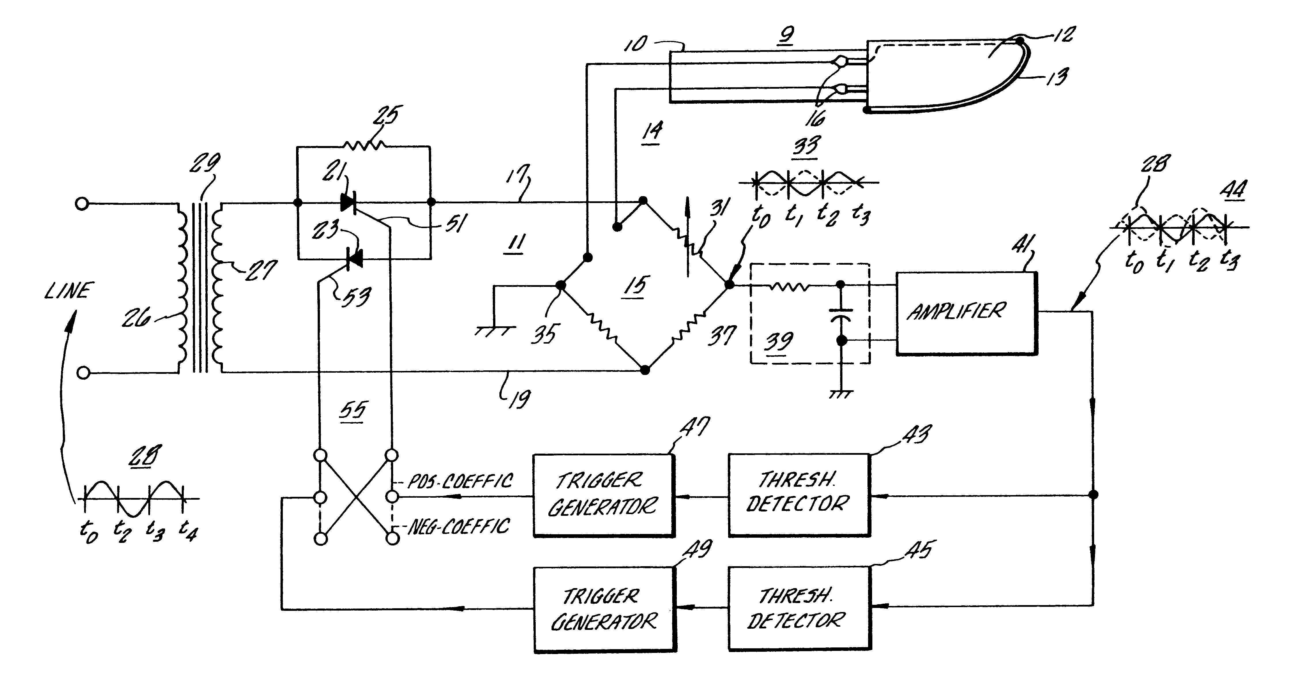
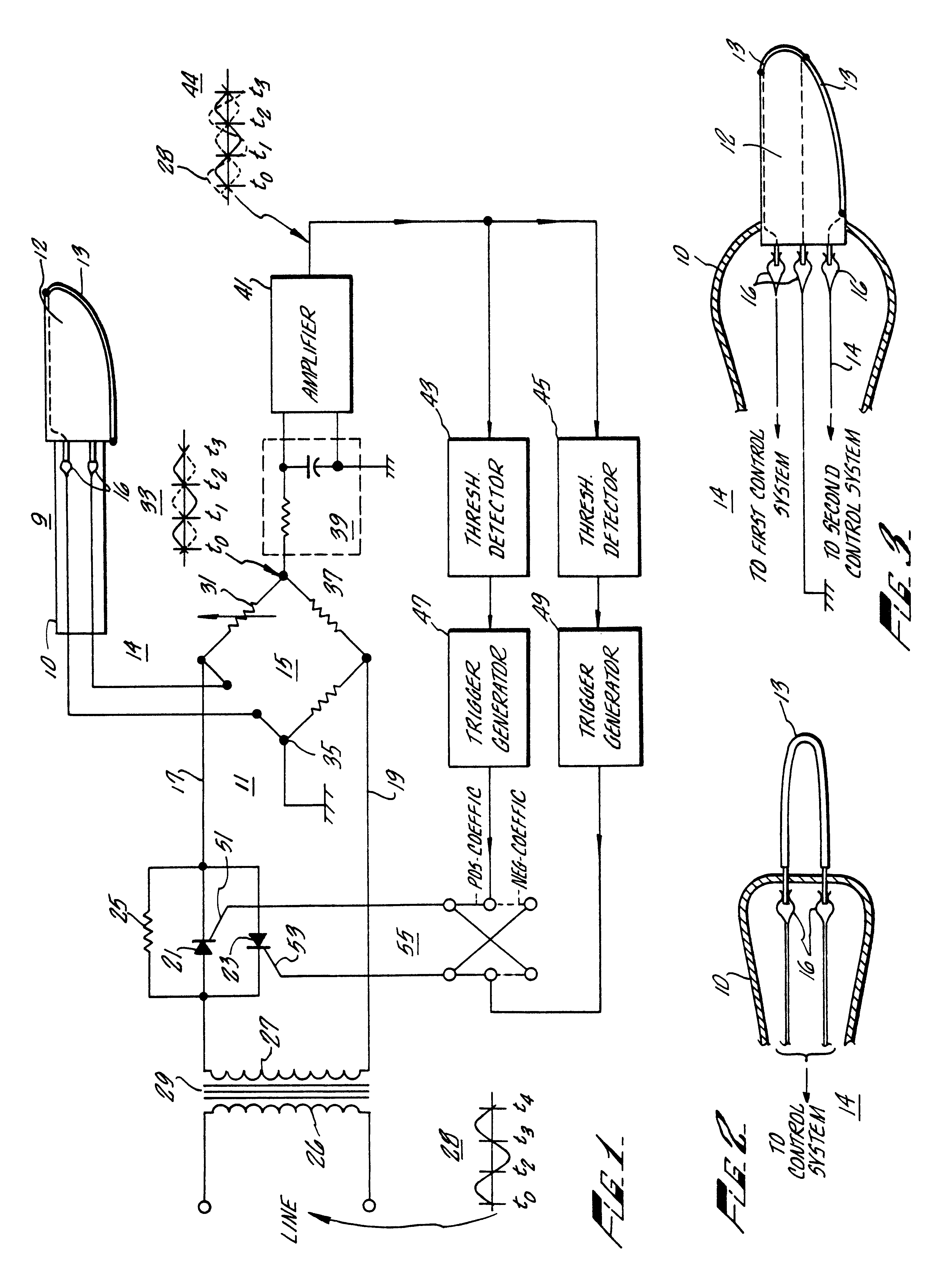
Referring now to FIG. 1 of the drawing, there is shown the surgical cutting instrument 9 connected to a temperature-measuring and power-controlling system 11. The cutting instrument 9 includes a thin ceramic card 12 in the desired shape of a surgical cutting blade which is detachable from the handle or holder 10. An electrically heated element 13 is disposed along the leading edge of the card 12 to form its cutting edge and is electrically connected to the control circuit through the cable 14 and the connectors 16. The element 13 may be a single filament attached to the edge of the card 12, for example, using conventional ceramic welding materials or may be a layer of electrically conductive material vapor-deposited along the edge of the card 12. Also, the heating element 13 may have sufficient cross-sectional area to be self-supporting as shown in FIG. 2, so that the blade 18 is formed entirely by the element 13 alone. The material used in the element 13 ideally should have a negat...


PUM

PropertyMeasurementUnit
Angleaaaaaaaaaa
Temperatureaaaaaaaaaa
Metallic bondaaaaaaaaaa

Abstract

Surgical cutting instrument includes an electrically heated cutting edge and an automatic control system for maintaining the cutting edge at a constant high temperature for sterilizing the blade, cutting tissue, and cauterizing the incised tissue to reduce hemorrhage from the cut surfaces of the tissues (hemostasis).

Description

BACKGROUND OF THE INVENTIONThe control of bleeding during surgery accounts for a major portion of the total time involved in an operation. The bleeding that occurs when tissue is incised obscures the surgeon's vision, reduces his precision and often dictates slow and elaborate procedures in surgical operations. Each bleeding vessel must be grasped in pincer-like clamps to stop the flow of blood and the tissue and vessel within each clamp must then be tied with pieces of fine thread. These ligated masses of tissue die and decompose and thus tend to retard healing and promote infection.SUMMARY OF THE INVENTIONAccordingly, the present invention provides a surgical cutting instrument having a cutting edge which is electrically heated to a constant high temperature for sterilizing the blade, cutting the tissue and cauterizing the surfaces of the incision, thereby allowing surgery to be more rapidly performed. This is accomplished in accordance with the illustrated embodiment of this inve...

Claims


Application Information

Patent Timeline
IPC IPC(8): A61B17/32A61B18/08A61B18/04A61B18/20A61B18/00A61B18/28G05D23/20G05D23/24A61B18/14A61B19/00
CPCA61B17/32A61B18/00A61B18/08A61B18/082G05D23/2401A61B18/28A61B2090/0813A61B2018/00005A61B2018/00107A61B2018/00666
Inventor SHAW, ROBERT F.
Owner THERMAL SCALPEL
Learn More