Vehicle frame front end device with collision buffering function

A frame and functional technology, applied in the field of automobile chassis, can solve the problems of inability to form a buffer, damage to parts, damage to the front beam of the frame and the longitudinal beam of the frame, etc., to extend the buffer time, reduce the degree of damage, and prolong the buffer time Effect

Pending Publication Date: 2018-11-06
JIANGLING MOTORS
View PDF0 Cites 1 Cited by
  • Summary
  • Abstract
  • Description
  • Claims
  • Application Information

AI Technical Summary

Problems solved by technology

When the impact position is high, the front beam of the frame deforms and collapses, and transmits the impact force to the longitudinal beam of the frame. Since the front beam of the frame and the longitudinal beam of the frame are approximately rigidly connected, the front beam of the frame and the longitudinal beam of the frame The beams are easy to be damaged at the same time; when the impact position is low, the lower protective beam deforms and collapses, and transmits the impact force to the lower protective beam connecting bracket, because the lower protective beam connecting bracket and the frame longitudinal beam are also approximately rigidly connected, and the lower protective beam The contact point (area) between the connecting bracket of the protective beam and the longitudinal beam of the frame is fixed, so that the lower protective beam and the connecting bracket of the lower protective beam cannot be moved back effectively, and thus cannot form an effective buffer
Therefore, the traditional front-end device of the frame does not have the buffer function, especially when the impact time is short and the impact is violent, the impact is a huge threat to the life of the occupants, and it is easy to cause a large number of parts to be damaged.

Method used


Image

  • Vehicle frame front end device with collision buffering function
  • Vehicle frame front end device with collision buffering function
  • Vehicle frame front end device with collision buffering function

Examples


Embodiment Construction

[0020] The present invention will be further described below with reference to accompanying drawing and specific embodiment:

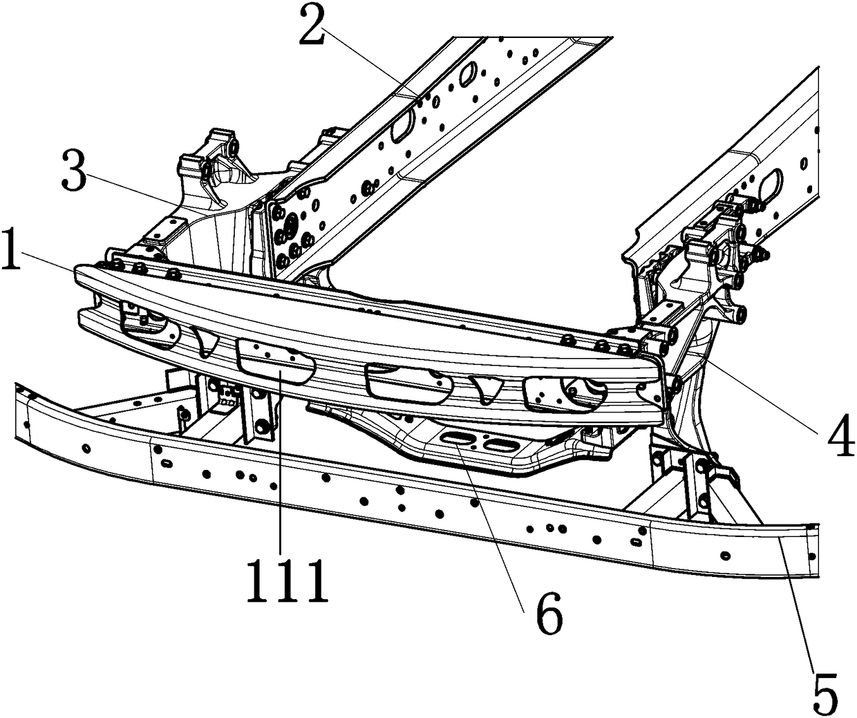
[0021] figure 1 It is a structural schematic diagram of the front end device of the vehicle frame with the function of collision buffering in this embodiment. The front-end device of the vehicle frame includes a vehicle frame front beam 1, a vehicle frame longitudinal beam 2, a front extension bracket 3, a leaf spring support 4, a lower protective beam 5 and a leaf spring support beam 6, and one end of the front extension bracket 3 is connected to the plate One end of the spring bracket 4 is fixedly connected into one, and then connected with the vehicle frame longitudinal beam 2; Connection, the leaf spring support beam 6 is installed on the side of the leaf spring support 4 .

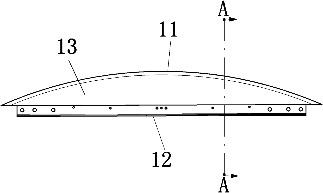
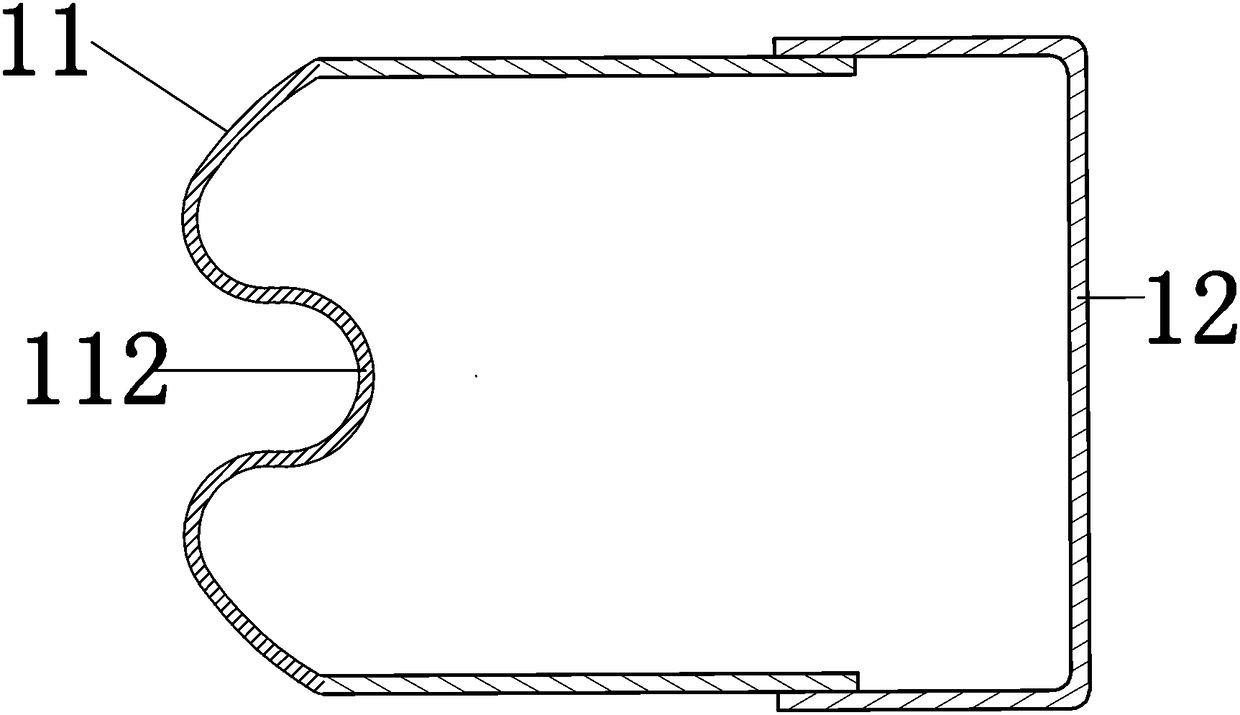
[0022] From figure 2 and image 3 It can be seen that the front beam 1 of the vehicle frame includes a front section 11 of the front beam and a rear section 12 of the fro...


PUM


Abstract

The invention relates to a vehicle frame front end device with a collision buffering function. The vehicle frame front end device comprises a vehicle frame front crossbeam, vehicle frame longitudinalbeams, a plate spring support crossbeam, a lower protective crossbeam, forward-extending supports and plate spring supports. One end of each forward-extending support is fixedly connected with one endof the corresponding plate spring support into a whole and connected with the corresponding vehicle frame longitudinal beam. The vehicle frame front crossbeam is connected with the other end of eachforward-extending support. The lower protective crossbeam is connected with the other end of each plate spring support. The plate spring support crossbeam is installed on the side portions of the plate spring supports. By the adoption of the vehicle frame front end device with the collision buffering function, impact energy can be effectively absorbed, buffering time is prolonged, the degree of harm to passengers can be reduced when a collision happens to a vehicle, and the number of damaged parts is reduced.

Description

technical field [0001] The invention relates to the technical field of automobile chassis, in particular to a vehicle frame front end device with a collision buffer function. Background technique [0002] The traditional front-end device of the frame includes the front beam of the frame, the longitudinal beam of the frame, the lower protective beam, the connecting bracket of the lower protective beam and the leaf spring support beam, wherein the front beam of the frame and the longitudinal beam of the frame form an approximately rigid connection through rivets or bolts , the lower protective beam is connected to the lower protective beam connecting bracket, and the lower protective beam connecting bracket forms an approximately rigid connection with the vehicle frame longitudinal beam through bolts. The front beam of the vehicle frame is a frame structure, the surface of the front beam of the vehicle frame is provided with through holes, and the lower protective beam is a ho...

Claims


Application Information

Patent Timeline
Patent Type & Authority Applications(China)
IPC IPC(8): B62D21/15
CPCB62D21/155
Inventor 张瑞峰范政武王艳武毛大为张婉盈
Owner JIANGLING MOTORS
Why Eureka
Try Eureka