
Light scattering sheet, light scattering composite sheet, and liquid crystal display

Inactive Publication Date: 2004-04-20
DAICEL CHEM IND LTD
View PDF19 Cites 90 Cited by
  • Summary
  • Abstract
  • Description
  • Claims
  • Application Information

AI Technical Summary

Benefits of technology

The inventors of the present invention made intensive investigations to accomplish the above objects and found that subjecting a plurality of resins varying in refractive index to spinodal decomposition gives an isotropic bicontinuous phase structure with ease and that by using a sheet having such a bicontinuous phase structure, a high order of directionality can be imparted to diffused light. The inventors further discovered that with a composite sheet composed of a light-scattering sheet and a polarizer sheet, an optical retardation film, a reflector or a transparent electrode layer, not only an image of high quality can be produced but also a liquid crystal display device can be manufactured easily and at low cost. It was further discovered that when the light-scattering sheet is disposed in a defined position in a reflecting type liquid crystal device, the durability of the reflecting type liquid crystal display device can be improved and, in addition, an image of high precision can be obtained. The present invention has been developed on the basis of the above findings.
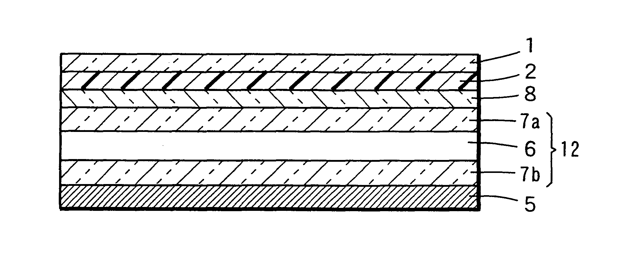
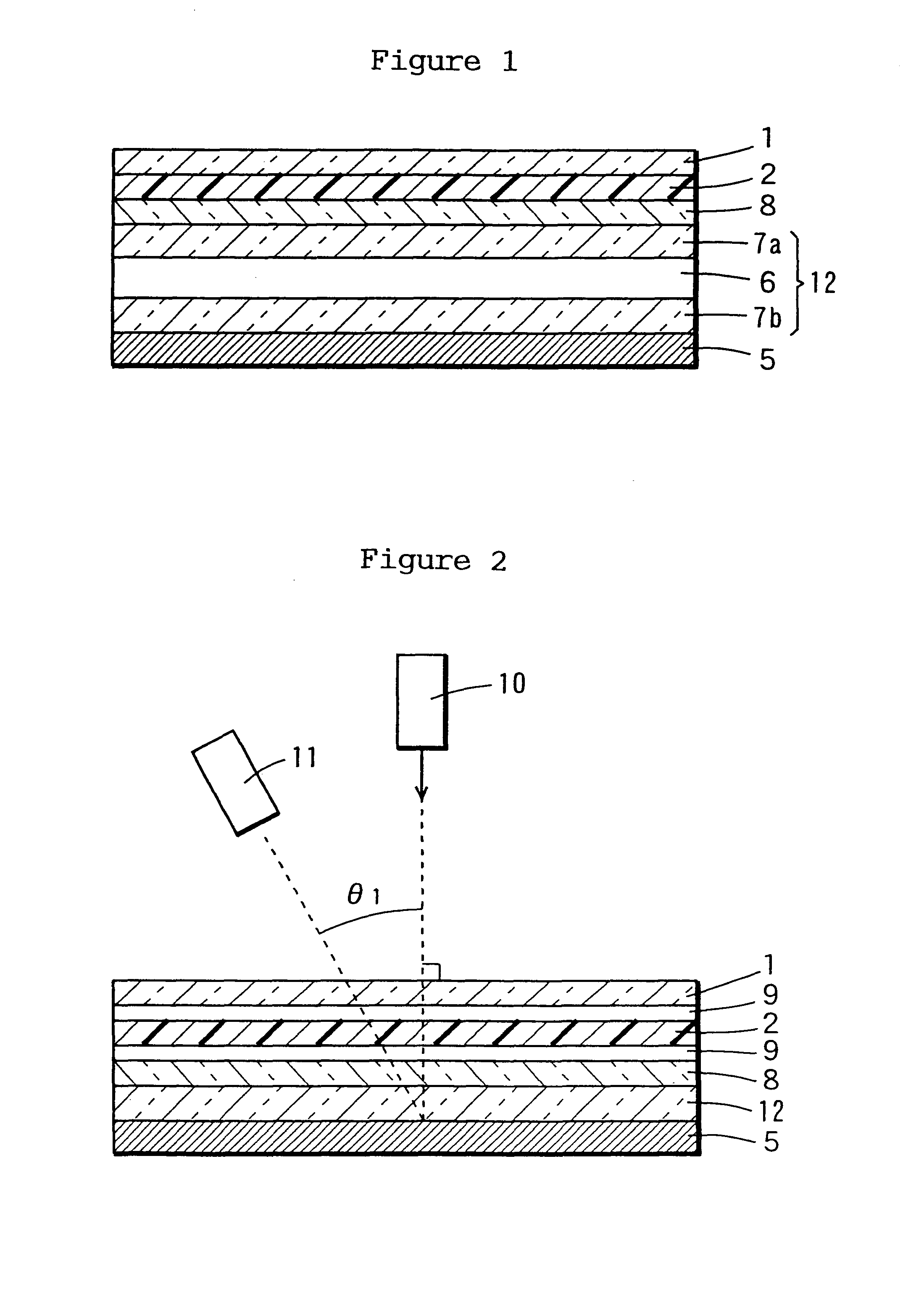
In fabricating a liquid crystal display device using a composite sheet, the composite sheet is preferably disposed (laminated) to the liquid crystal cell in such a manner that the light-scattering sheet of the composite sheet will come close to the liquid crystal cell. For example, in fabricating a reflecting type liquid crystal display device by disposing a composite sheet composed of a light-scattering sheet and a polarizer (or an optical retardation film) on the viewer side of the liquid crystal cell, the composite sheet is preferably disposed (laminated) with the light-scattering sheet facing the liquid crystal cell (that is to say with the polarizer (or optical retardation film) facing the viewer). When the composite sheet is disposed with its light-scattering sheet in proximity with the liquid crystal, a further improvement is realized in the clarity of images.

Problems solved by technology

However, it requires an elaborate processing technique and a high cost.
In case a color filter is used, the proportion of loss of reflected light is increased and the above diffusion plate system cannot impart enough brightness to the display screen.
In order to increase this directionality with the diffusion-reflector system, it is necessary to precisely control the geometry and distribution pattern of reflector surface irregularities but this is a costly procedure.
Therefore, when a light-scattering layer is formed on the surface of such a polarizer plate, the surface of the display device (that is the light-scattering sheet) becomes vulnerable to marring so that the visibility of the screen of the reflecting type liquid crystal display apparatus is lowered to adversely affect the image quality.
In particular, it becomes difficult to maintain the image quality over a long time.
Furthermore, because a double image, namely the liquid crystal image and the image from the light-scattering layer is formed, the sharpness of the image is sacrificed (blurred image) to adversely affect the image quality.
Meanwhile, a resin sheet as polymerized by utilizing holography for imparting directionality to a transmitting type light-scattering sheet is known (The synopsis of Lectures at Japanese Society of Liquid Crystal Science, 1998) but the production process is complicated and costly.

Method used


Image

  • Light scattering sheet, light scattering composite sheet, and liquid crystal display
  • Light scattering sheet, light scattering composite sheet, and liquid crystal display
  • Light scattering sheet, light scattering composite sheet, and liquid crystal display

Examples


example 1

In 400 weight parts of a mixed solvent of methylene chloride and methanol (9 / 1, by weight) were dissolved 50 weight parts of poly(methyl methacrylate) (PMMA-4) and 50 weight parts of poly(styrene-co-acrylonitrile) (SAN-4). This solution was cast on a glass plate to form an 8 .mu.m-thick layer. The glass plate was heated on a hot plate at 280.degree. C. for 1 minute. After this heat treatment, the glass plate-resin sheet was dipped in a cold water bath. The sheet was peeled from the glass plate, spread on a frame and dried (thickness: 10 .mu.m). When examined with a transmission light microscope, the sheet thus obtained was found to have an intermediate structure between a bicontinuous structure and a particle dispersion (droplet) structure, the average interphase distance of the continuous phases being about 6 .mu.m. The total light transmittance of this sheet was 93%. A schematic diagram depicting the phase structure observed by transmission light microscopy is presented in FIG. 19...

example 2

Except that the temperature of heat treatment was changed to 250.degree. C. and the duration of heat treatment was changed to 3 minutes, the procedure of Example 1 was otherwise followed. The resulting sheet was examined with a transmission light microscope. As a result, the sheet was found to have an intermediate structure between the bicontinuous phase structure and the droplet phase structure, with an average interphase distance of about 6 .mu.m.

reference example 1

In 900 weight parts of a mixed solvent of methylene chloride and methanol (9 / 1, by volume) were dissolved 80 weight parts of cellulose triacetate (CEL-1) flakes. Then, 20 weight parts of PMMA powder (PMMA-5) was mixed and the mixture was cast to give a 150 .mu.m-thick sheet. When examined with a transmission light microscope, the sheet was found to have a droplet phase structure, the average diameter of droplets being 3 .mu.m. The total light transmittance of the sheet was 92%.

The performance characteristics of the light diffusing sheets obtained in Examples 1 and 2 and Reference Example 1 were evaluated by the following procedures.

(Directionality 1)

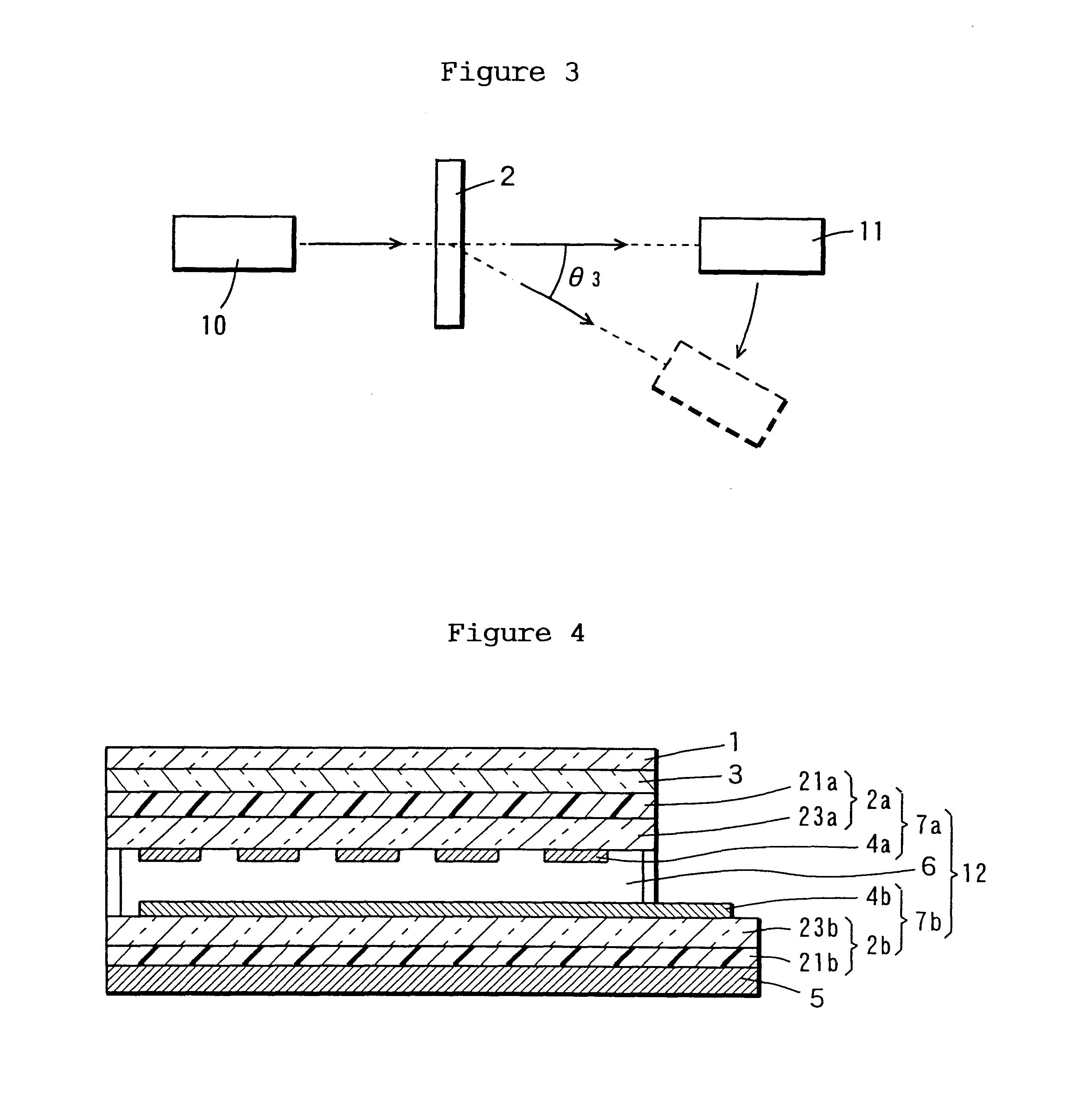
Using each of the light-diffusing sheets obtained as above, the reflecting type LCD model device shown in FIG. 2 was constructed. The device was illuminated with a laser beam (Nihon Kagaku ENG NEO-20MS) in a vertical direction from the front and the intensity (diffusion intensity) of reflected light at the diffusion angle .theta.1 was me...


PUM

PropertyMeasurementUnit
Angleaaaaaaaaaa
Angleaaaaaaaaaa
Angleaaaaaaaaaa

Abstract

A light-scattering sheet having a phase separation structure comprised of a plurality of solid components varying in refractive index is used to construct a liquid crystal display device. In a first embodiment, the light-scattering sheet is disposed in a defined position within a reflecting LCD device. Thus, in a reflecting LCD device comprising a liquid crystal cell constituted of a transparent front electrode plate having a substrate carrying a transparent conductive layer, a back electrode plate having a substrate carrying a conductive layer and a liquid crystal and, as disposed forwardly of the liquid crystal cell, a polarizer, the light-scattering sheet is interposed (i) between the polarizer and the front electrode plate or (ii) between the back electrode plate and a reflector disposed behind the back electrode plate. Alternatively, (iii) the substrate sheet may be constituted of the light-scattering sheet. In a second embodiment, a light-scattering sheet having an isotropic bicontinuous phase structure comprised of a plurality of polymers varying in refractive index is used.

Description

The present invention relates to a light-scattering sheet (film) for liquid crystal devices useful for the high-luminance display of images, a method of producing the sheet, a light-scattering composite sheet utilizing said sheet, a liquid crystal display device, and a method of producing said light-scattering composite sheet.The liquid crystal display (LCD) device is utilized broadly in the display segments of personal computers, word processors, LC televisions, chronometers, desktop calculators and other electrical and electronic products. Since the liquid crystal by itself does not emit light, a backlight for illuminating the liquid crystal cell from the back side is used in liquid crystal display devices to the exclusion of low-luminance applications such as watches and desktop calculators.Recent years have witnessed advances in the construction of infrastructures for telecommunications systems such as internets and in the network consolidation of information through the compute...

Claims


Application Information

Patent Timeline
IPC IPC(8): G02F1/13G02B5/02G02B5/30G02F1/1335
CPCG02B5/0226G02B5/0278G02B5/0284G02F1/133504G02B5/3033Y10T428/24942Y10T428/10Y10T428/1086C09K2323/00C09K2323/06Y10T428/31507Y10T428/3154Y10T428/31663Y10T428/31725Y10T428/31786Y10T428/31855Y10T428/31935Y10T428/31971G02B5/021G02B5/0268G02B2006/12071
Inventor JINNAI, HIROSHITAKEMOTO, HIROYUKITAKAHASHI, HIROSHIHIRAISHI, MASANORINISHIDA, YOSHIYUKI
Owner DAICEL CHEM IND LTD
Learn More