
Guidewire

a technology of guidewires and guidewires, which is applied in the field of guidewires, can solve the problems of inability to fully insert flexible access guidewires, disadvantages of instrumentation placement, and inconvenient placement of instruments

Inactive Publication Date: 2004-04-06
APPL MEDICAL RESOURCES CORP
View PDF28 Cites 114 Cited by
  • Summary
  • Abstract
  • Description
  • Claims
  • Application Information

AI Technical Summary

Benefits of technology

The present invention is a guidewire for urological procedures that has a highly flexible, kink-resistant tip for easy access. The guidewire has three regions of specific flexibility: a floppy distal tip, a non-slippery central section, and a medium degree of lubricity proximal section. The guidewire is designed to allow for easy placement of instruments and can be easily replaced without the need for a separate exchange sheath. The guidewire is also designed to prevent separation of the components joined by the operator, ensuring safety during the procedure. The guidewire is made using a mechanical lock that joins dissimilar metals, providing a stronger joint that reduces the risk of failure.

Problems solved by technology

However, once the flexible access guidewire is in place, it is ill-suited for the placement of instruments.
By comparison, stiffer guidewires facilitate the insertion of instruments, because they tend to straighten out the anatomy in a way that flexible guidewires cannot.
Unfortunately, this four-step procedure was required every time one guidewire was exchanged for another guidewire.
In some cases, the flexible access guidewire was incapable of being fully inserted, typically due to some obstruction such as a urological stone or stricture in the urological system.
Alternatively, in those cases where the slippery guidewire was able to achieve the ultimate, desired position in the urological system, it also presented disadvantages for the placement of instrumentation.
Slippery guidewires tend to be so lubricious that they can actually fall out of the urological system, purely due to gravitational forces.
These processes are very operator dependent, and if not properly accomplished, can result in separation of the joined components within the patient.

Method used


Image

  • Guidewire
  • Guidewire
  • Guidewire

Examples


Embodiment Construction

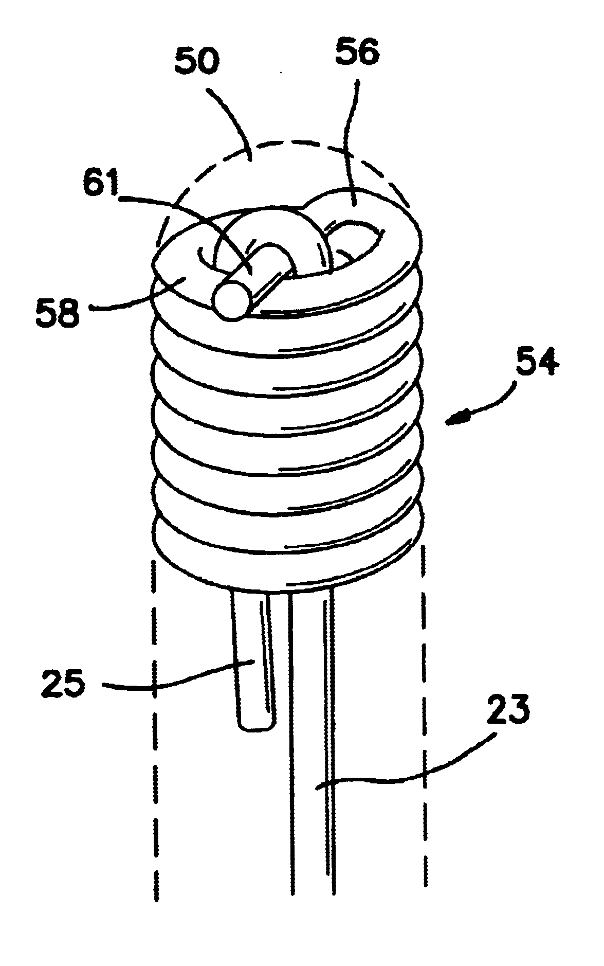
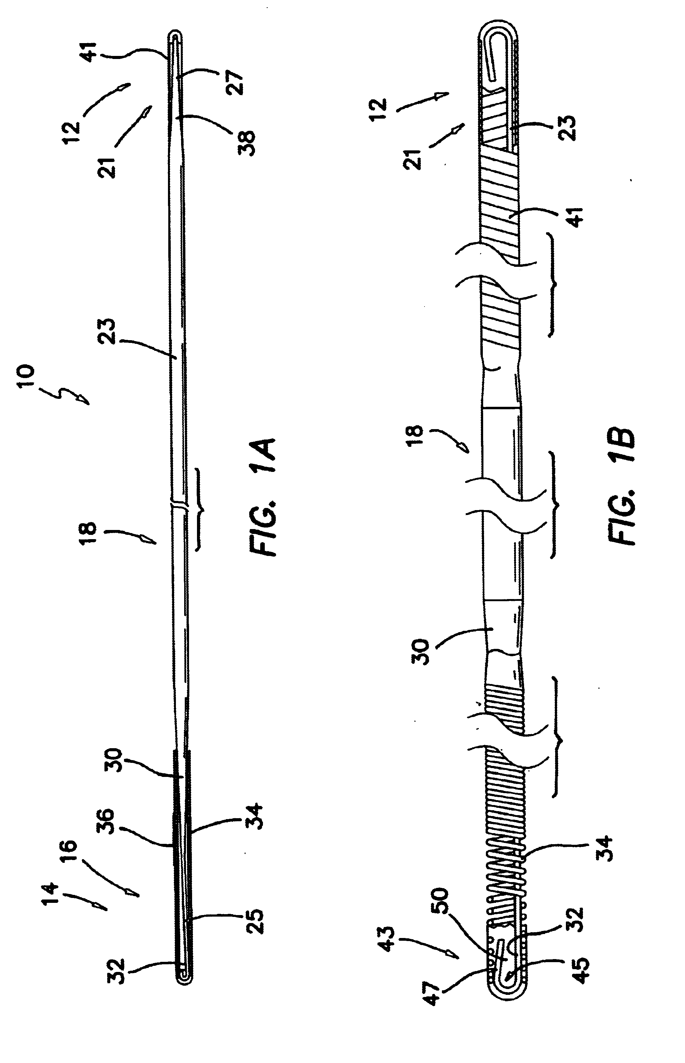
A urological guidewire, as illustrated in FIG. 1, and designated generally by the reference numeral 10. The guidewire 10 has an elongate configuration and stems between a proximal end 12 and a distal end 14. The guidewire 10 is adapted for use in accessing distal locations within the urinary tract by inserting the distal end 14 into the urethra of the patient and advancing the distal end 14 to the operative site. Various instruments can then be advanced over the guidewire 10 to perform an operative procedure at the operative site.

In the illustrated embodiment, the urological guidewire 10 includes a distal section 16 with a first flexibility, a first lubricity, and a first length. The central section 18 has a second flexibility, a second lubricity, and a second length. Similarly, a proximal section 21 has a third flexibility, a third lubricity, and a third length. In a preferred embodiment, the first length of the distal section 16 is 14.4 mm and the third length of the proximal sect...


PUM


Abstract

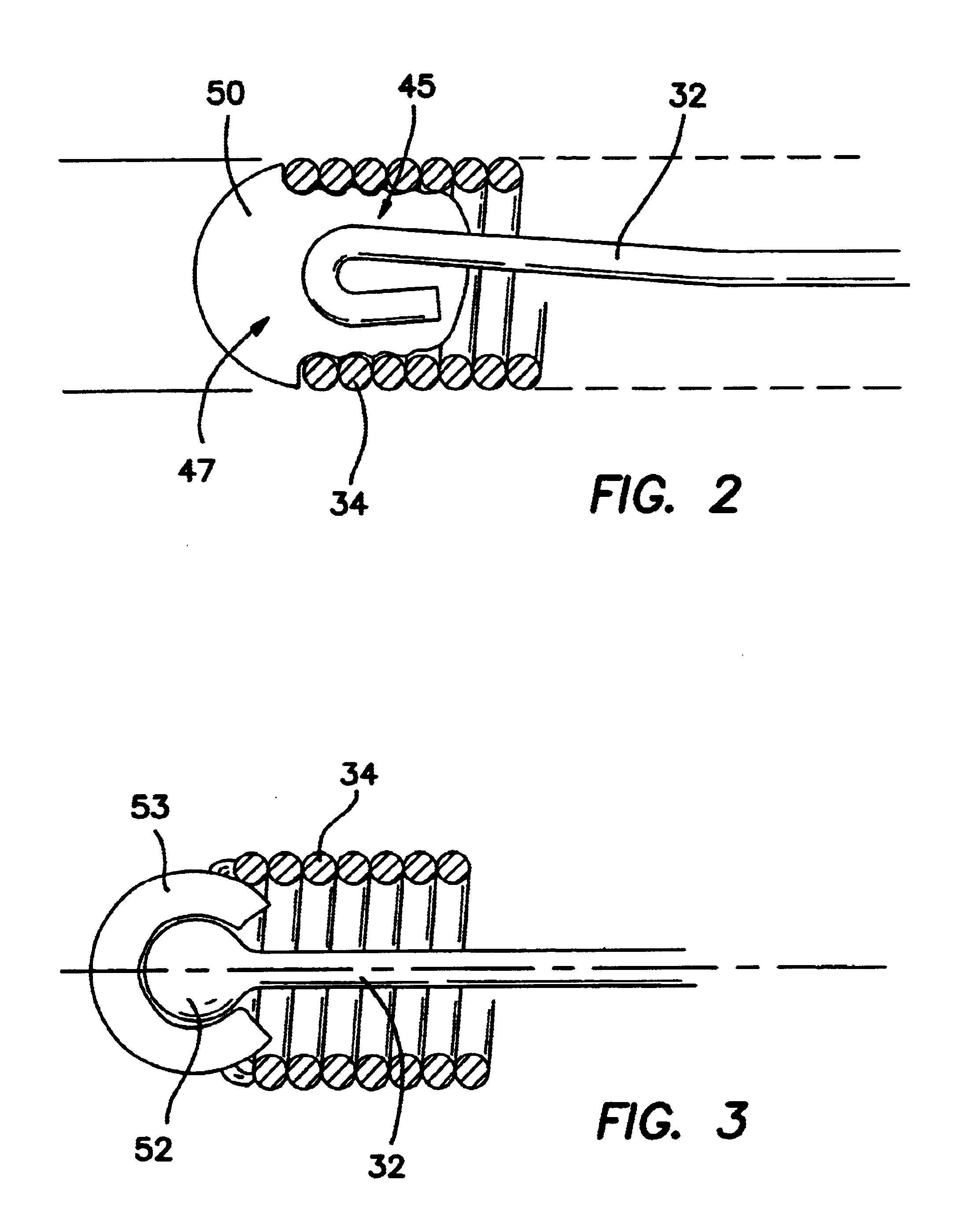
A urological guidewire includes a core formed of a first metallic material and extending toward an end of the guidewire. A coil having a plurality of convolutions is disposed around the core at the end of the guidewire, the coil being formed of a second metallic material different than the first metallic material. A mechanical interlock is formed to inhibit separation of the different materials forming the coil and the core. The mechanical interlock may include an enlargement at the end of the core and a bonding material fixing the enlargement to the coil. The convolutions may include a penultimate convolution with a first radius of curvature and an ultimate convolution having a second, shorter radius of curvature to form a bridge. In this case, portions of the core can be bent back on themselves and directed over or around the bridge to form the mechanical interlock.

Description

1. Field of the InventionThis invention relates generally to guidewires and, more specifically, to urological guidewires adapted for insertion and instrument guidance through the urological conduit.2. Discussion of Related ArtThe first step in a typical endoscopic urological procedure is placement of a guidewire into the patient's urological system. When operatively disposed, the guidewire typically extends from outside the patient, through the urethra, the bladder, the ureter, and into the kidney. The guidewire allows a variety of specialized tools, such as catheters and endoscopes, to be repeatedly positioned in the urological system with ease, safety, and efficiency.Urological guidewires of the past have typically been provided with properties relating to flexibility, lubricity, and stiffness. Each guidewire has tended to emphasize one of these properties along its entire length, in order to provide certain advantages at different points in the procedure. For example, due to the ...

Claims


Application Information

Patent Timeline
Patent Type & Authority Patents(United States)
IPC IPC(8): A61B1/307A61M25/09
CPCA61M25/09A61B1/307A61M2025/09083A61M2025/09175
Inventor CLAYMAN, RALPH V.PINGLETON, EDWARD D.VANDENBROEK, FRANSSAKAKINE, GHASSAN
Owner APPL MEDICAL RESOURCES CORP
Learn More