
Airfoil anti-icing assembly and method

a technology of airfoil and assembly, applied in the direction of de-icing equipment, machines/engines, hot gas positive displacement engine plants, etc., can solve the problem of attendant additional labor and material costs for the manufacture of systems employing such components

Inactive Publication Date: 2004-03-09
ROHR INC
View PDF14 Cites 61 Cited by
  • Summary
  • Abstract
  • Description
  • Claims
  • Application Information

AI Technical Summary

Benefits of technology

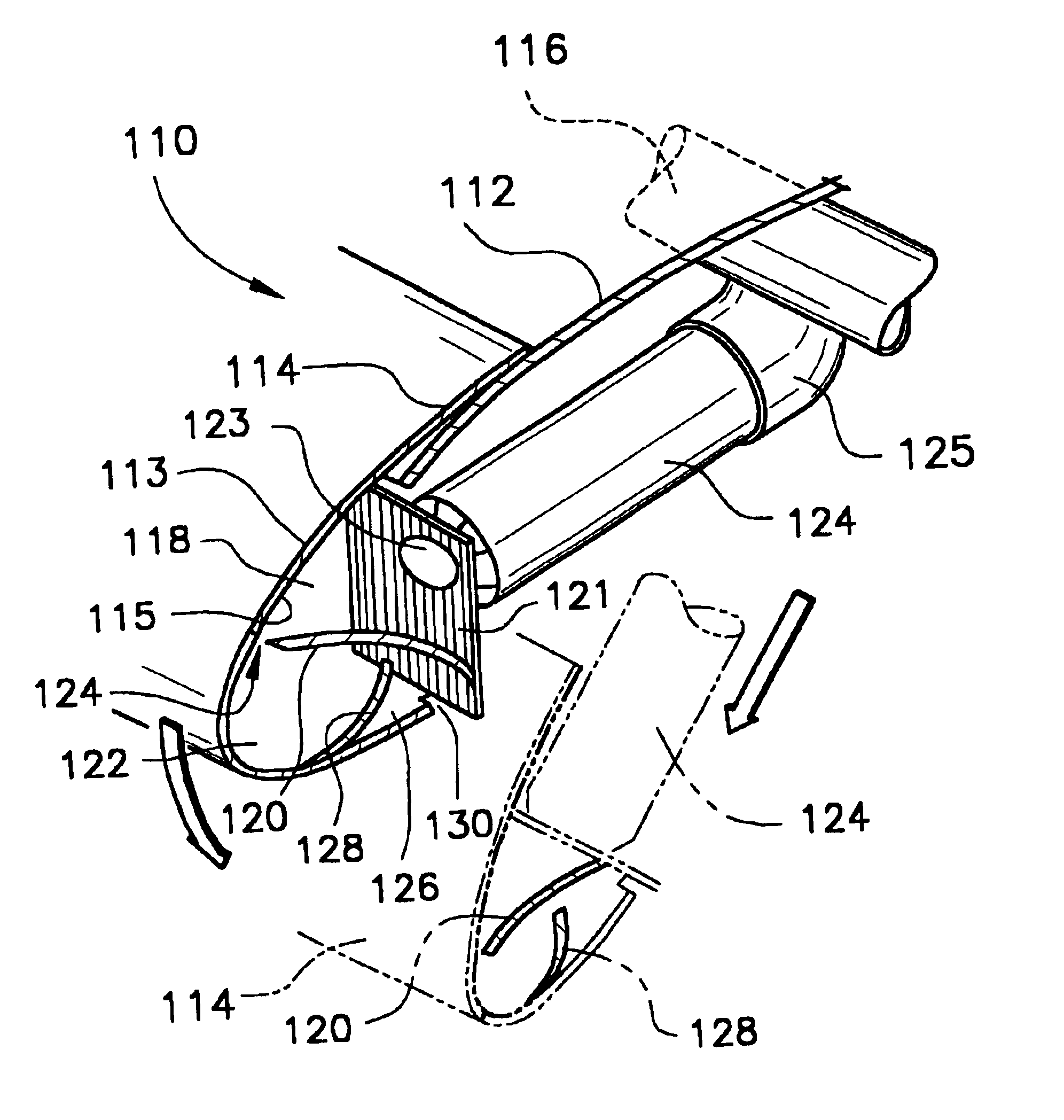
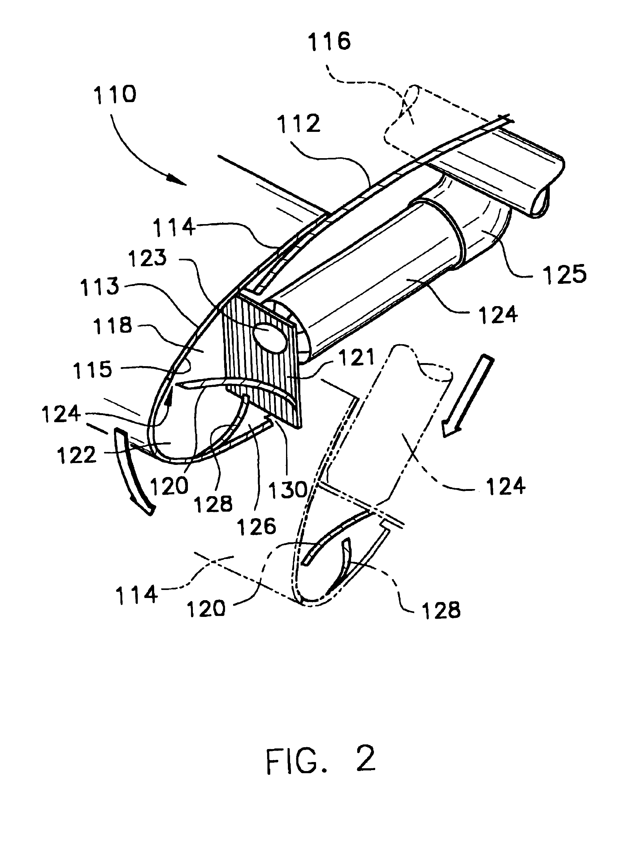
This patent is about an invention that prevents ice formation on airfoils such as aircraft wings and slats without using tubes or spray ducts. Instead, hot gases are introduced into the airfoil through an inlet and outlet plenum, which causes the hot gases to swirl and effectively heat the exterior surface of the airfoil. This invention avoids the need for additional materials and labor costs associated with traditional anti-icing systems.

Problems solved by technology

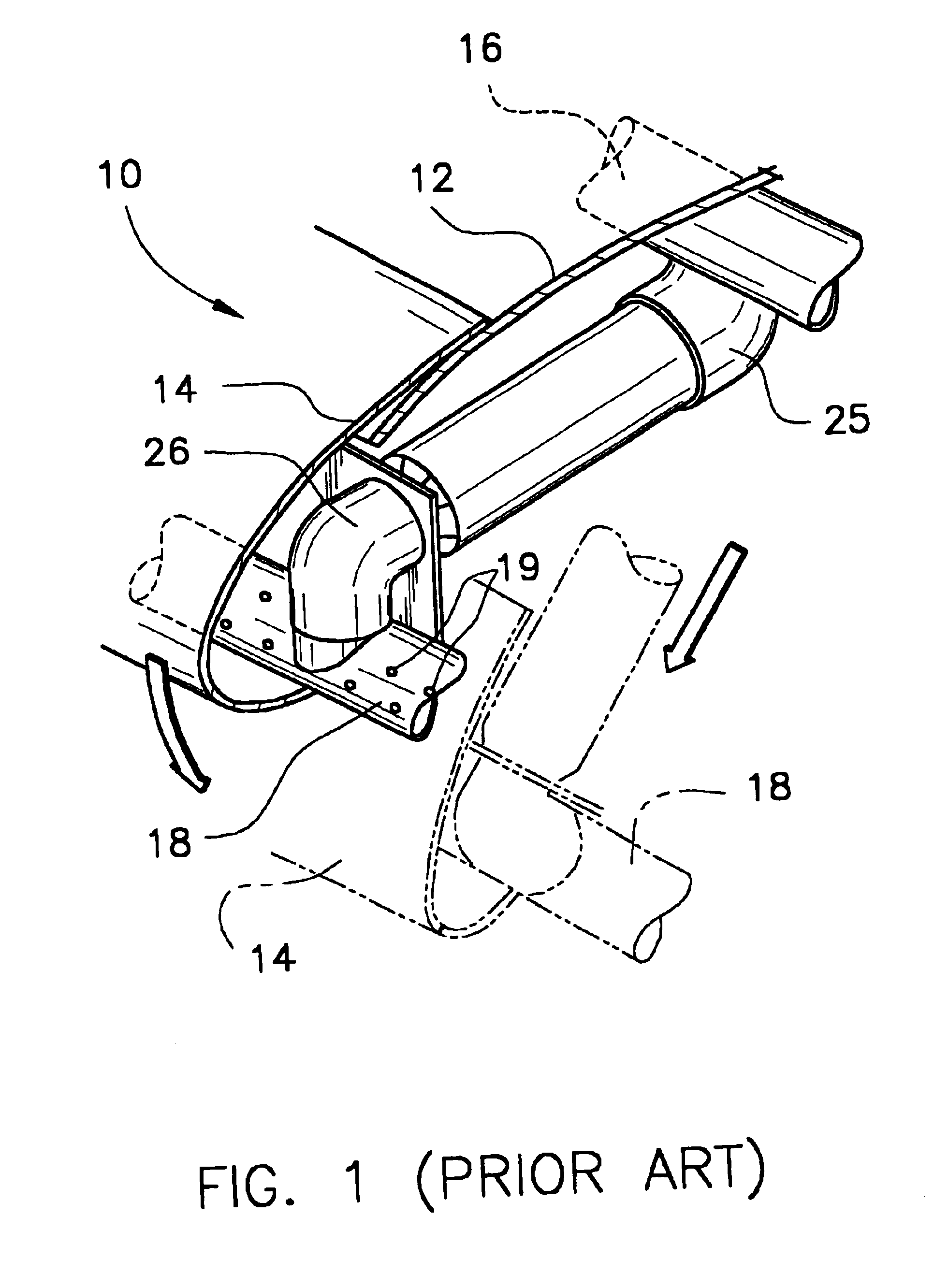
First, such tubes and spray ducts require additional materials, and thereby results in attendant additional labor and material costs for the manufacture of systems employing such components.

Method used


Image

  • Airfoil anti-icing assembly and method
  • Airfoil anti-icing assembly and method
  • Airfoil anti-icing assembly and method

Examples


Embodiment Construction

A computer modeling analysis of the invention was conducted using a computational grid generator (i.e. GAMBIT, a product of FLUENT, Inc., Lebanon, N.H.) and a two-dimensional (2-D) Navier-Stokes flow solver program (i.e. FLUENT, a product of FLUENT, Inc., Lebanon, N.H.).

The computational model was created using an unstructured, triangular mesh. The airfoil model is a 2-D cross-section of a leading-edge using NACA airfoil coordinates. This mesh was created using the grid generator GAMBIT. More detailed information about this grid generator is included in the GAMBIT User's Guide (FLUENT, Inc., Lebanon, N.H., May 1998). FIG. 6 displays a typical example of an unstructured mesh in an airfoil model generated in GAMBIT. These models used an average of 3000 nodes to define the grid.

Each airfoil model contained an inlet, outlet, and throat section. For consistency between all of the models, the ratio of outlet area to throat area used was set at a constant value of 6:1, while the ratio of t...


PUM


Abstract

An anti-icing assembly for an airfoil such as an aircraft wing or slat comprises: (a) an airfoil having an exterior surface and interior wall defining an interior cavity, and bottom, middle and side portions all adjacent to the interior cavity; (b) an inlet plenum integral to the airfoil, wherein the inlet plenum comprises (i) an inlet baffle capable of directing hot gases into the airfoil interior cavity and (ii) a throat section interfacing the inlet plenum and airfoil interior cavity; and (c) an outlet plenum integral to the airfoil, wherein the outlet plenum comprises an outlet baffle capable of directing hot gases from the airfoil interior cavity. The airfoil anti-icing method of this invention comprises providing hot gases such as jet engine bleed air to the airfoil assembly of this invention, swirling the hot gases within the airfoil interior cavity, and discharging the hot gases from the airfoil interior cavity through the airfoil outlet end. The system of this invention comprises a source of hot gases, typically jet engine bleed air, and the airfoil assembly of this invention.

Description

BACKGROUND OF INVENTION1. Field of the InventionThis invention relates to an airfoil anti-icing assembly, method and system. More particularly, the assembly, method and system of this invention use hot gases which are directed into the interior cavity of the airfoil and caused to swirl, thereby effecting sufficient heat transfer to avoid icing of the exterior surface of airfoils such as aircraft wings and slats. The hot gases are directed into the airfoil interior cavity without using tubes or spray ducts.2. Background InformationThe use of aircraft jet engine exhaust gases or bleed air in aircraft anti-icing systems to prevent the formation of ice on aircraft wings, engine inlets, etc. is well known to those skilled in the art. For example, co-assigned U.S. Pat. Nos. 4,688,745 and Re. 36,215 disclose a jet engine anti-icing system for preventing jet engine icing, in which hot gas, such as air, is obtained from the jet engine and directed to an annular housing located around the lea...

Claims


Application Information

Patent Timeline
Patent Type & Authority Patents(United States)
IPC IPC(8): B64D15/00B64D15/04
CPCB64D15/04
Inventor DUPONT, HENRY MORGAN
Owner ROHR INC
Learn More