
Stackable ring network including burst transmission of data packet

a ring network and data packet technology, applied in data switching networks, frequency-division multiplexes, instruments, etc., can solve the problems of wasting system bandwidth, nothing useful is transmitted, and it is not yet possible to make a decision on which unit should be the next master

Inactive Publication Date: 2004-01-27
HEWLETT-PACKARD ENTERPRISE DEV LP
View PDF6 Cites 53 Cited by
  • Summary
  • Abstract
  • Description
  • Claims
  • Application Information

AI Technical Summary

Benefits of technology

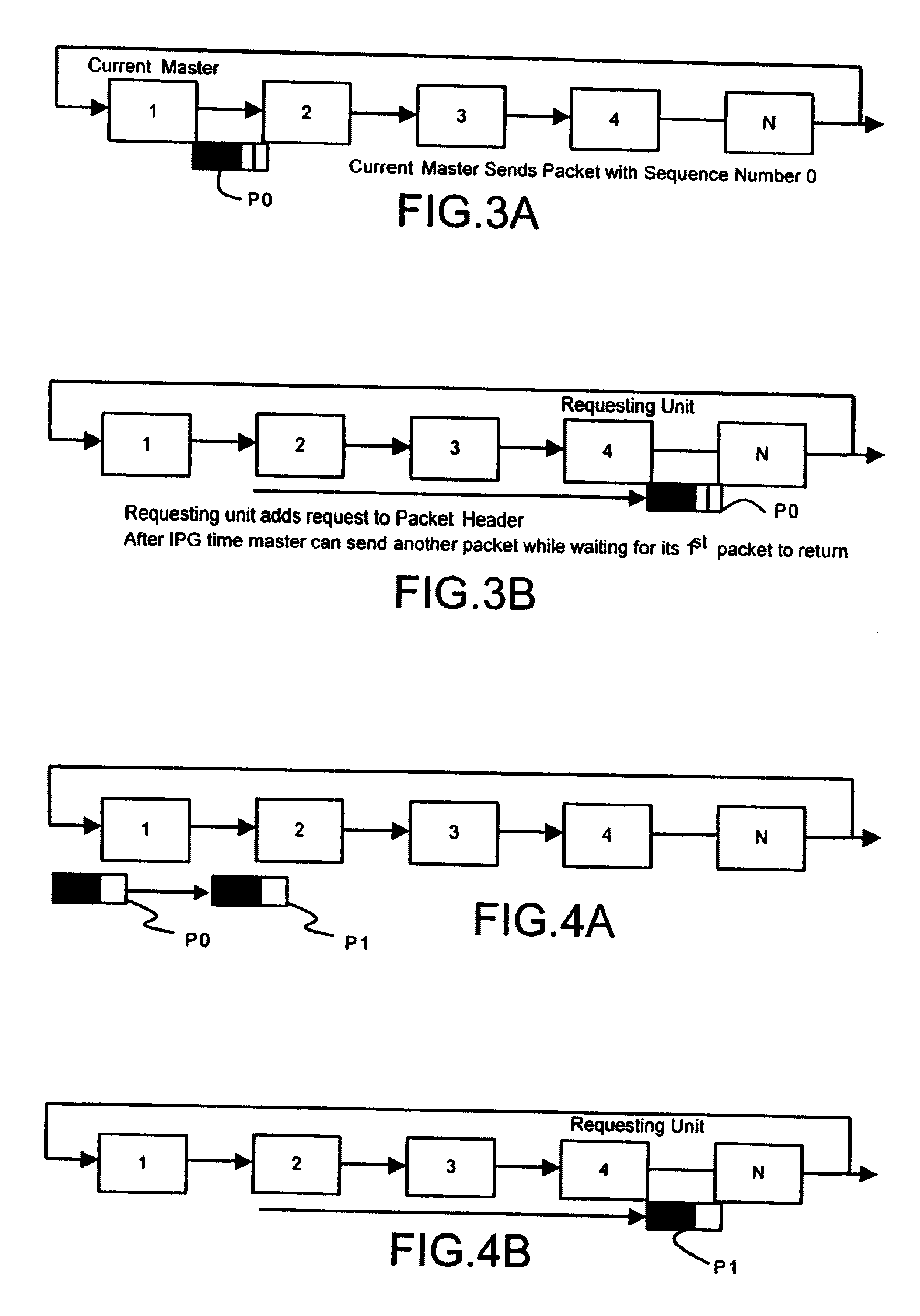
The present invention is aimed at improving the performance of a ring of stacked units with distributed arbitration. It provides a solution for ensuring that packets can be efficiently transmitted through the ring without causing delays or wasting bandwidth. The invention involves allowing the master unit to transmit another packet with an incremented sequence number, even if the master unit has not yet received the header of the first packet. This ensures that the master unit can make an arbitration decision and grant a new mastership of the ring to a new master unit. The invention also includes a mechanism for preventing multiple units from setting requests in the header of a packet, which can cause delays and waste bandwidth. Overall, the invention improves the speed and efficiency of the ring of stacked units with distributed arbitration.

Problems solved by technology

However, if the ring is large and the packet being transmitted is small then the master will have finished transmitting the packet long before it as received the header of the packet back again and so it cannot yet make a decision on which unit should be the next master.
Therefore nothing useful is transmitted and the bandwidth of the system is wasted.

Method used


Image

  • Stackable ring network including burst transmission of data packet
  • Stackable ring network including burst transmission of data packet
  • Stackable ring network including burst transmission of data packet

Examples


Embodiment Construction

FIG. 1 illustrates schematically three stacked hub units, designated `unit 1`, `unit 2`, and `unit 3`, connected together to form a rinse for the circulation of packets that may be put on the ring by any one of the units. It will be understood that only one unit at any time may in normal operation place packets on the ring. The mode of such a unit is `MASTER`, the mode of other units is `REPEAT` as indicated in FIG. 6. Each of the units is similar and for convenience only the middle unit will be described in detail. This unit is a hub unit 10 which has in addition to its ordinary ports (not shown) two duplex cascade ports, a first port 11, conveniently called `down` port, and a second port 12, conveniently called `up` port. The unit 10 includes two signal paths between these two ports. A first path, which for various reasons is preferably termed the arbitration path, proceeds from the `down` port 11 of the unit to the `up` port 12. It is convenient to subdivide the functions of the ...


PUM


Abstract

A stackable network unit which can form a ring with other units has a master mode in which it can place packets on the ring, so that they can be ultimately forwarded from other units, and a repeat mode in which it can make a request for transfer of mastership of the ring, inserting bits in a header of an arbitration packet. If a master unit has completed the transmission of a packet and, preferably, after the required inter-packet gap has elapsed, it has not yet received an arbitration header to permit the making of an arbitration decision it can transmit a subsequent packet. The header information of this packet indicates to the other units that this subsequent packet is part of a burst of packets and the other units should not set requests in the header of this packet because this packet would not be used for arbitration. The master unit indicates the nature of the subsequent packet by setting a sequence number in the header of the packet to distinguish it and following packets in a burst from the 'first' packet which is the one used to pick up requests from the units that may need to become the master unit.

Description

The present invention relates to stackable units in packet-based communication systems and in particular to stackable hub units which can be `stacked` or connected in a ring so that the units form a single logical entity.BACKGROUND TO THE INVENTIONWhen units are stacked to form a single logical device such as a hub or switch, a user connected to a port of any one of the units can send packets to or receive packets from users connected to any of the ports on any of the units, as if all the ports were ports of a single multi-port device. In such a system, the units may be connected to form a closed path or ring by means of which packets can circulate from the unit having the port at which they are received to the unit having the port from which they need to be forwarded.It is necessary to provide some means of arbitration between requests by the units for access to the ring, that is to say for the ability to place a packet on the ring. This may be achieved in practice, as disclosed in...

Claims


Application Information

Patent Timeline
Patent Type & Authority Patents(United States)
IPC IPC(8): H04L12/433H04L12/427
CPCH04L12/433
Inventor GAVIN, VINCENTQUINLAN, UNADE PAOR, DENISECREEDON, TADHGSTAPLETON, NICHOLAS M
Owner HEWLETT-PACKARD ENTERPRISE DEV LP
Learn More