
Scale on an apparatus for measuring displacement

a technology of displacement and scale, which is applied in the direction of slide gauges, instruments, using mechanical means, etc., can solve problems such as detection errors and measurement errors

Inactive Publication Date: 2004-01-13
MITUTOYO CORP
View PDF4 Cites 58 Cited by
  • Summary
  • Abstract
  • Description
  • Claims
  • Application Information

AI Technical Summary

Benefits of technology

Material having a high solvent resistance, such as polyimid and epoxy coating material and the like, is suitable for the coating layer. It is desirable that the portion of the coating layer contacting the scale cover be cleaned and activated by plasma radiation so as to enhance adhesiveness between the coating layer and the scale cover. A material which can be coated at low temperature, for example, an ultraviolet hardening agent, is desirably used for the coating layer such that the rectangular grating can be prevented from deforming. If the scale member is entirely surrounded with the coating layer, a higher protection from contaminants is further provided.

Problems solved by technology

Thereby contaminated coolant and oil cause measurement errors.
In some types of oil and non-water-solvent coolants, chlorine and sulfur may cause chemical reaction with the rectangular grating 12 made from copper to make them corroded, to disrupt the rectangular grating 12 and to result in detection error.

Method used


Image

  • Scale on an apparatus for measuring displacement
  • Scale on an apparatus for measuring displacement
  • Scale on an apparatus for measuring displacement

Examples


first embodiment

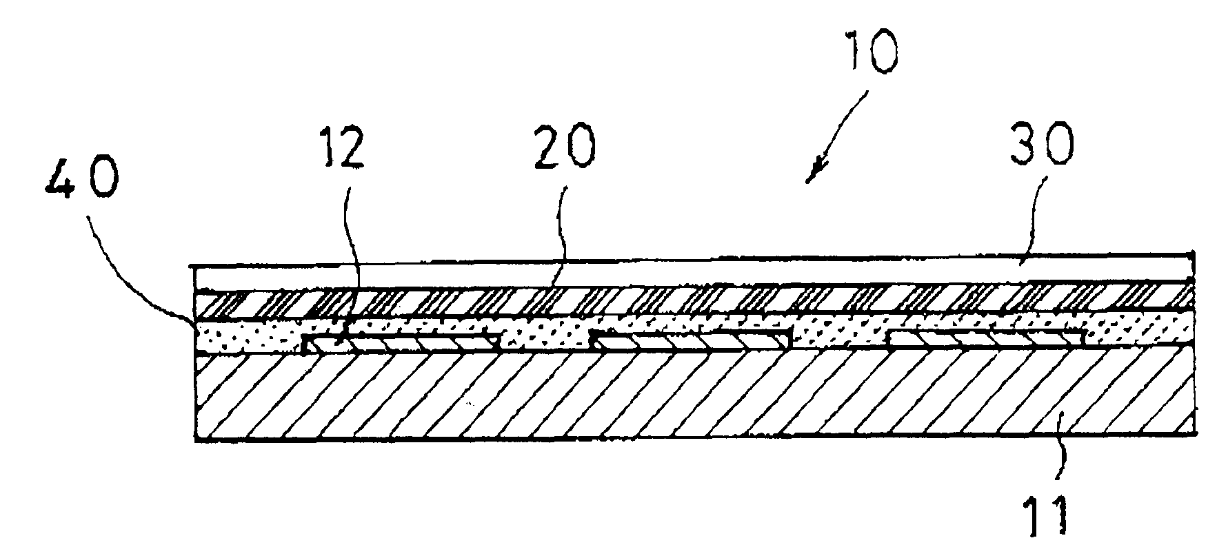
Referring to the figures, the preferred embodiment of the present invention will be explained next. FIG. 1 shows a cross sectional view representative of a scale on an apparatus for measuring displacement of the The scale comprises a scale member 10 having a plurality of rectangular gratings arranged with a periodic pattern on the glass epoxy substrate 11 and the like, a coating layer 40 covered on the side of the scale member 10 which a plurality of rectangular gratings 12, a scale cover (film layer) 30 which functions as a protective layer, and a scale forming material bonded to the outer portion of the coating layer 40 an adhesive layer 20 so as to keep contaminant or oil from intruding between the rectangular grating 12 and the adhesive layer 20 being for example an adhesive tape and the like.

The scale comprises the coating layer 40 cleaned, activated and made rough by radiating plasma after it is coated on the side of the scale on which the rectangular grating 12 are deposited...

second embodiment

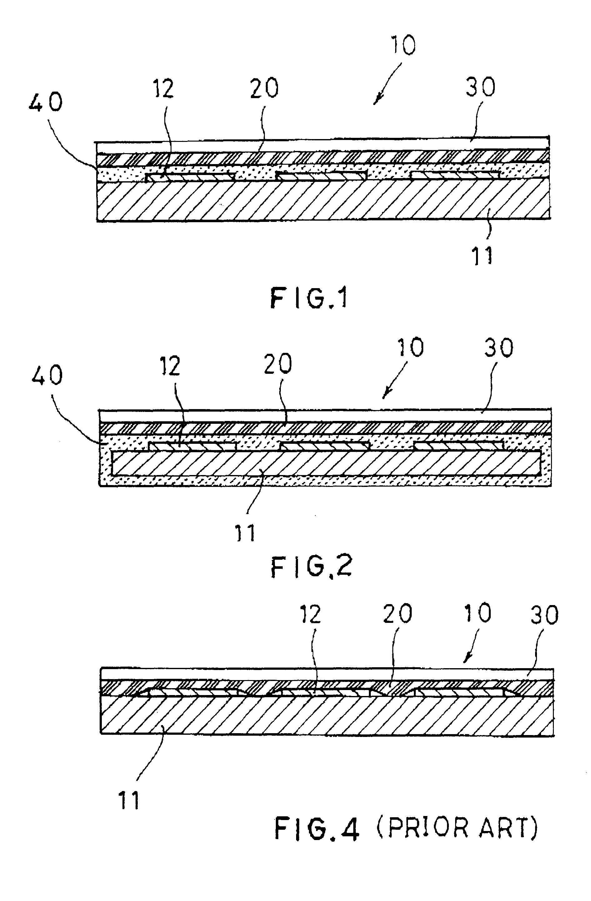
FIG. 2 shows a cross sectional view representative of a scale of an apparatus for measuring displacement of the This embodiment shows that the coating layer 40 covers not only the side of the scale member 10 on which rectangular grating 12 is deposited, but also the reverse side of it. In this case, in order to obtain a high adhesion upon bonding, the scale cover 30 is is desirably bonded on the adhesive layer 20 after the reverse side of the rectangular grating 12 is plasma irradiated for a rough surface thereon.

As described above, since the coating layer covers not only on the side of the scale member 10 on which the rectangular grating 12 are deposited, but also entirely surrounds the scale member including the electrodes and the scale substrate, it prevent a harmful contaminant or oil from intruding between the rectangular grating 12 and the adhesive layer 20.As a result, the present invention brings a great advantage that provides reliability of a scale of an apparatus for mea...


PUM


Abstract

A scale for an apparatus for measuring displacement is enclosed. It comprises a scale member having a plurality of rectangular gratings arranged in a periodic pattern on the glass epoxy substrate and the like, a coating layer covered on the side of the scale member on which a plural of the rectangular gratings are formed, a scale cover (film layer) which functions as a protective layer, and a scale forming material bonded to the outer portion of the coating layer by an adhesive layer so as to keep contaminants, oil or particles from intruding between the rectangular grating and the adhesive layer, for example an adhesive tape and the like.

Description

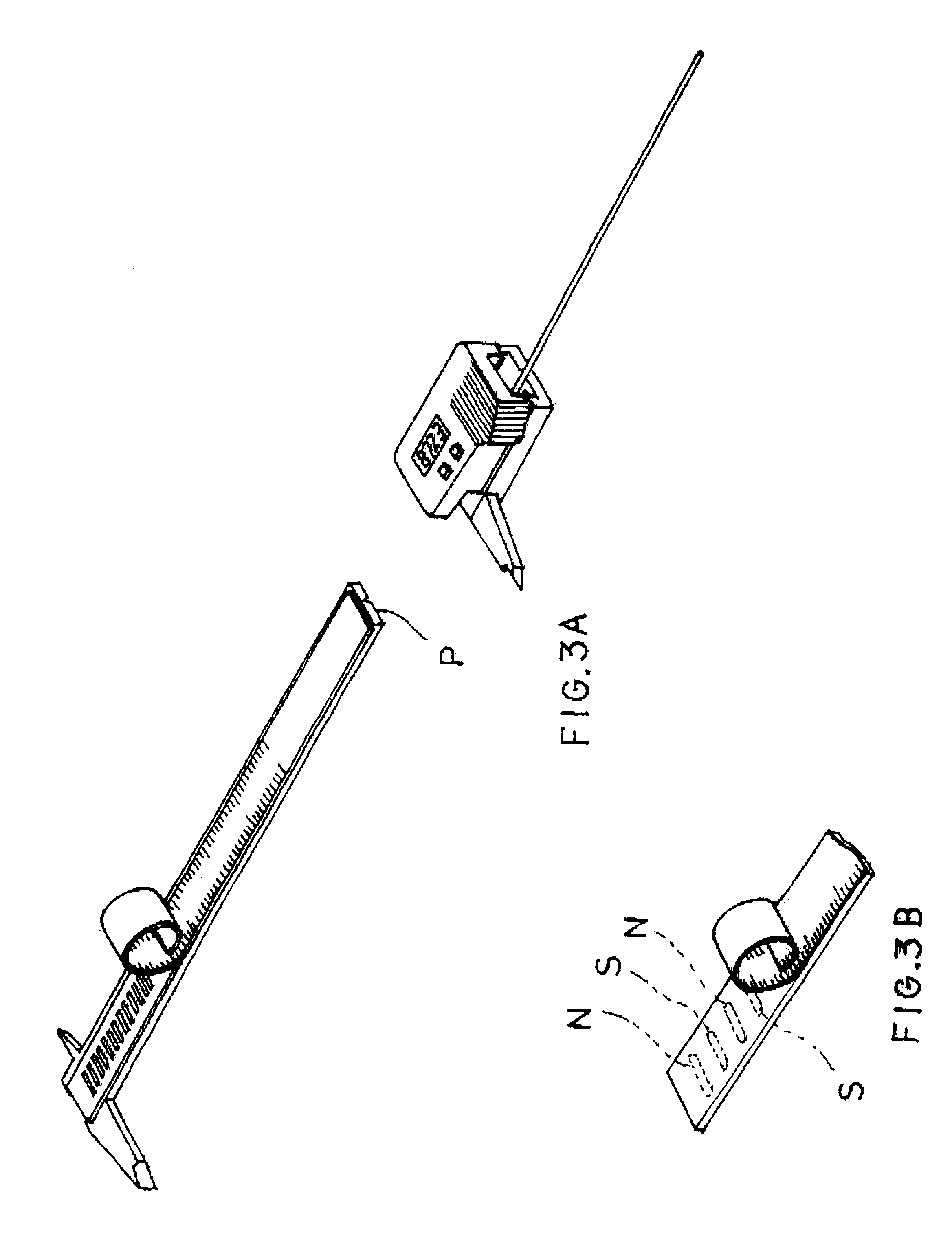
1. Field of the InventionThis invention relates to a scale on an apparatus for measuring displacement and more particularly to a scale providing a high environmental resistance on an apparatus for measuring displacement.2. Related Art of the InventionA scale on an apparatus for measuring displacement, for example, an electronic caliper disclosed in U.S. Pat. No. 5,973,494 to Karl G. Mareliez et al, is bonded to the top surface of a slider's beam assembly (denoted as P in FIG. 3A, showing the present invention). Such a the scale includes generally an elongated printed circuit board. A plurality of rectangular gratings 12 are spaced apart along the printed circuit board in an aperiodic pattern on a glass-epoxy substrate 11. The scale includes also a scale cover 30 which is deposited onto the top surface of a plural of rectangular gratings 12 by for example an adhesive tape or the like. The scale cover 30 serves as a protector for the adhesive layer 20. The protector 30 can also includ...

Claims


Application Information

Patent Timeline
Patent Type & Authority Patents(United States)
IPC IPC(8): G01B3/20G01B7/00G01D5/245
CPCG01B3/205
Inventor SASAKI, KOUJIOOYAMA, YOSHIKAZUKOIZUMI, HIROSHISHINPOU, NOBUYUKITAKAHASHI, SEIGO
Owner MITUTOYO CORP
Learn More