
Two-piece decorative medallion

a decorative medallion and two-piece technology, applied in the field of decorative medallions, can solve the problems of difficult detachment of fixtures, inconvenient installation, and inconvenient construction of medallions in shapes and designs previously prohibitively expensiv

Inactive Publication Date: 2003-12-23
STYLE MARK
View PDF13 Cites 9 Cited by
  • Summary
  • Abstract
  • Description
  • Claims
  • Application Information

AI Technical Summary

Problems solved by technology

The advent of these newer materials has prompted construction of medallions in shapes and designs that previously would have been prohibitively expensive.
The installation is not so simple or economical, however, when retro-fitting or remodeling an existing construction.
Often detaching a fixture can be difficult, with some fixtures being very delicate and / or awkward to handle.
Further, some older fixtures may be secured in unusual ways and / or may have paint-filled or rounded-over screw heads that make the fasteners hard to undo.
Once the fixture is detached, the electrical wiring to the fixture is disconnected, which as discussed below is not necessarily an easy task.
The overall installation process is thus rather time consuming.
For the average homeowner, even a small electrical task may be troubling, and potentially unsafe, especially if the older wiring is in place in.
Older wiring, for example, often does not meet current building codes and may pose dangers due to lack of proper grounding and lack of ground fault interruption (GFI) switches.
Even properly grounded wiring may be dangerous if the insulation has become brittle and cracked over time.
While the safest course is for the homeowner to hire an electrician to remove and remount the fixture, it greatly increases the cost of the task.

Method used


Image

  • Two-piece decorative medallion
  • Two-piece decorative medallion
  • Two-piece decorative medallion

Examples


Embodiment Construction

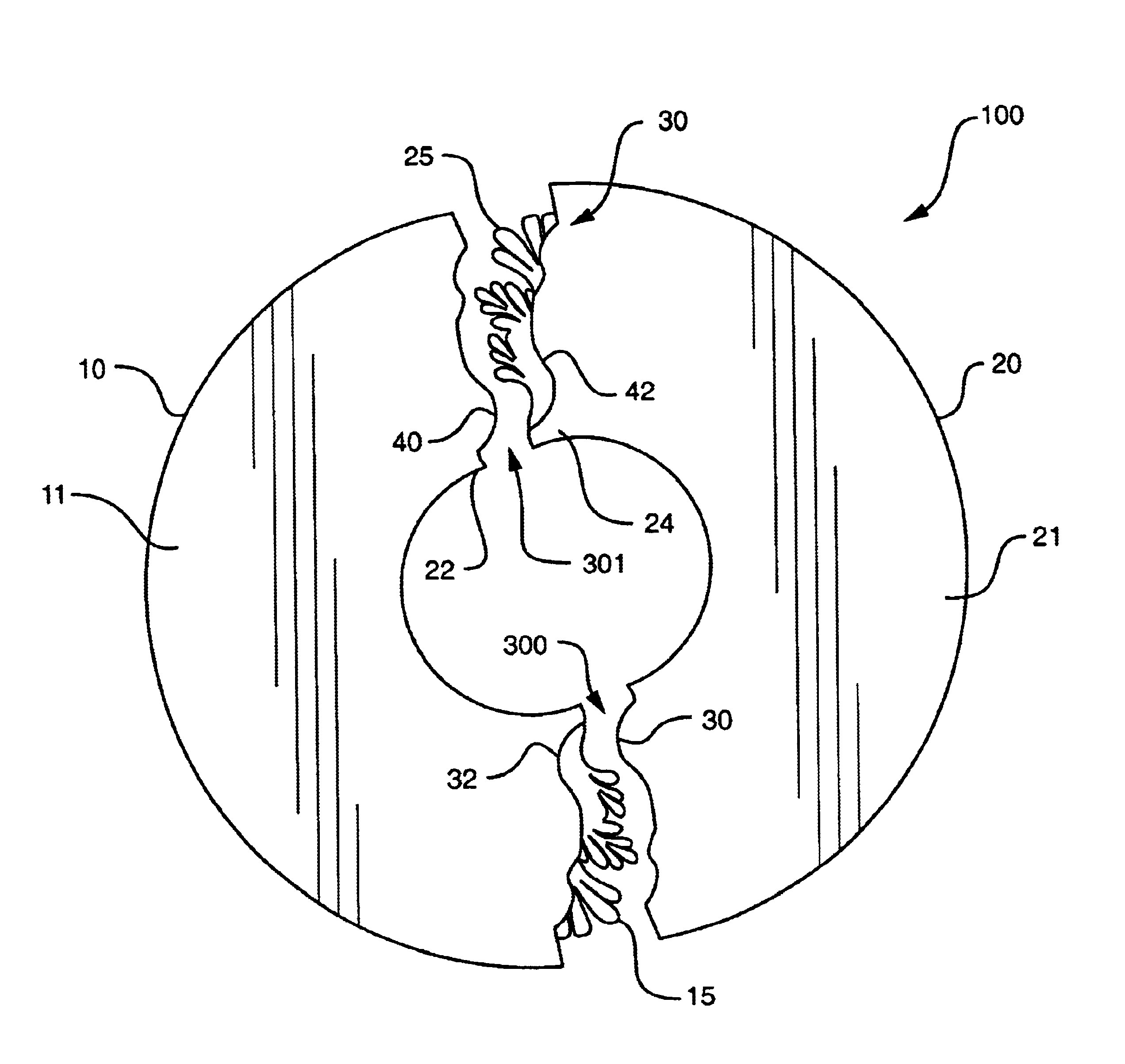
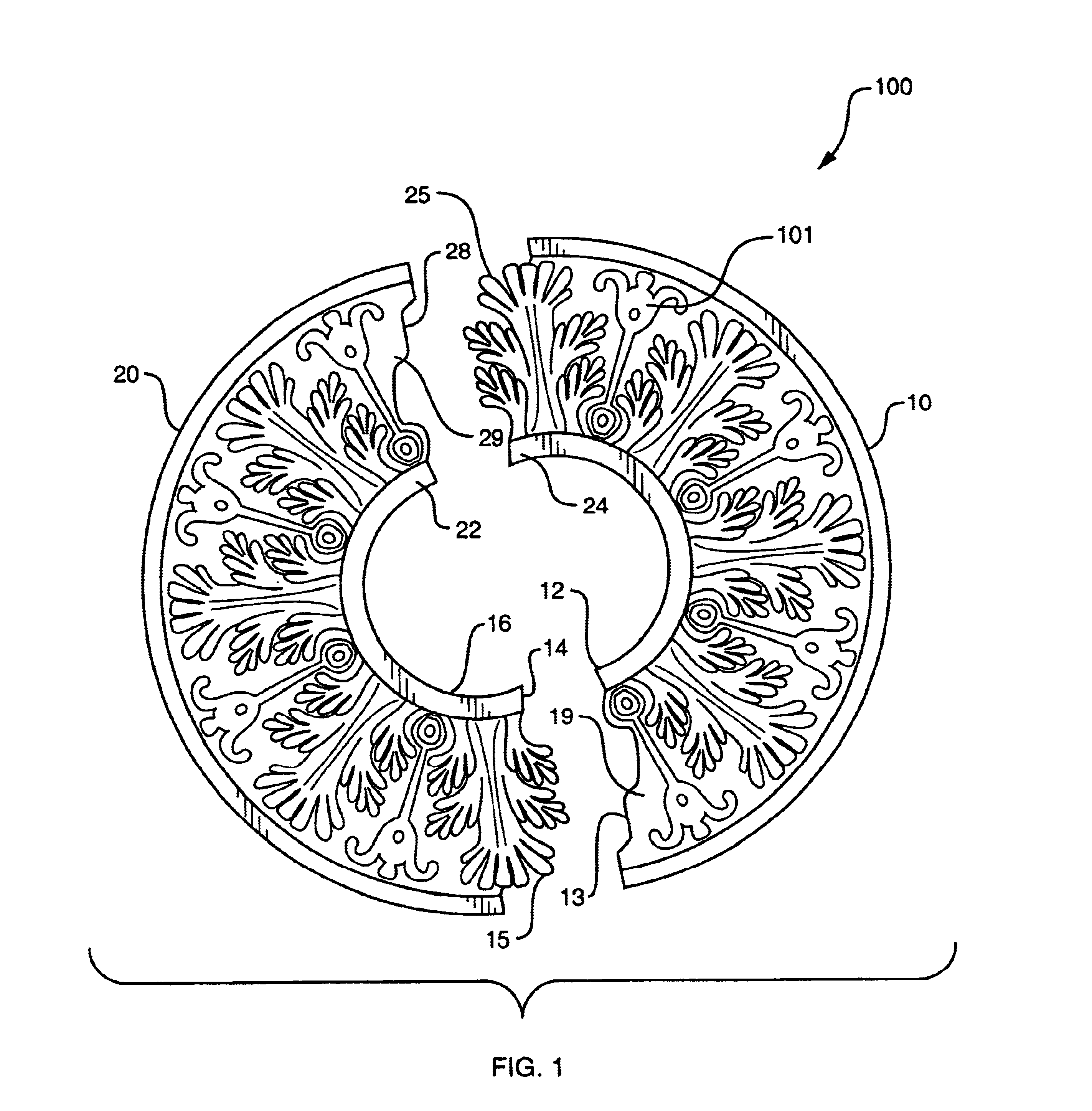
. 1 depicts a front view of two pieces 10 and 20 which, when combined, constitute a ceiling medallion 100. FIG. 4 depicts the assembled medallion. The pieces 10 and 20 may be constructed out of any type of rigid material that can be cut, sculpted or molded into decorative designs, such as solid wood, plaster, a bonded wood product such as Medium Density Fiberboard (MDF), or Architectural Foam which due to its ease of manufacture and relatively light weight is generally preferred.

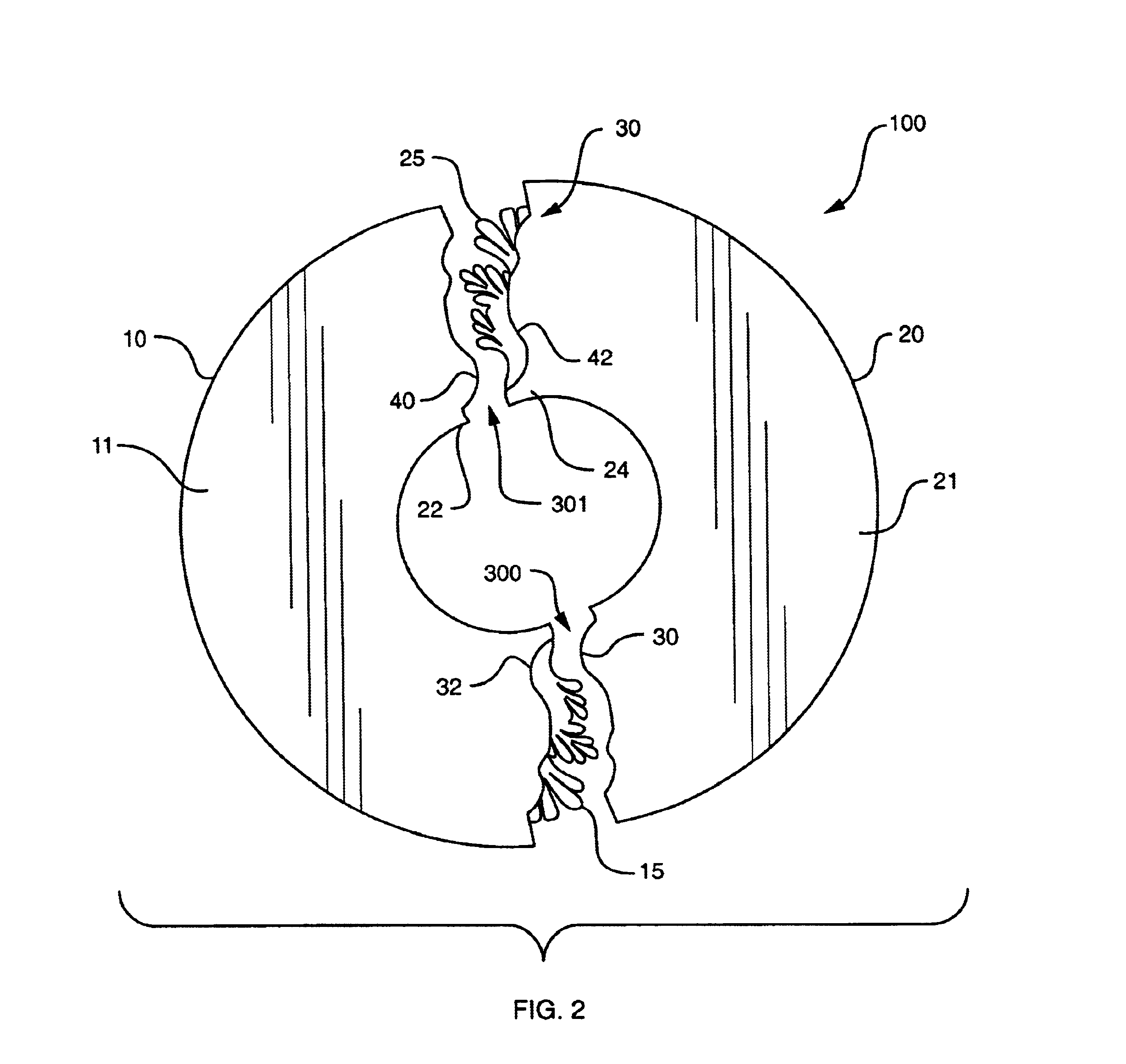
Referring again to FIG. 1, the pieces 10 and 20 are preferably decorated with surface ornamentation 101 or other relief work, to add to the visual appeal. The ornamentation is also employed as part of a novel method of joining the two medallion pieces, which include at either end, overlapping members 15 and 25 and underledges 18 and 28, respectively. Each overlapping member 15 and 25 is cut in an outline that follows the surface ornamentation of the medallion. The outline follows one or more prominent featur...


PUM


Abstract

A decorative medallion consists of two pieces that may be assembled about a mounted fixture. The medallion pieces are decorated with surface ornamentation to add to their visual appeal. A first piece of the medallion includes at a first end an overlapping member whose outline follows prominent features in the surface ornamentation, and at a second end an underledge designed to receive the overlapping member of the second piece. The second piece similarly includes an underledge that is designed to receive the overlapping member of the first piece. The respective overlapping members have recessed edges that are shaped to include one or more alignment features, such as protrusions and concave receiving portions. The underledges are shaped to slideably mate with the corresponding alignment features of the respective overlapping members, and thus, include various corresponding concave receiving portions and protrusions. The alignment features allow the two pieces to slide relative to one another into both lateral and vertical alignment, and the respective outlines of the top surfaces of the overlapping members essentially hide the seams in the surface ornamentation.

Description

1. Field of the InventionThe present invention relates to decorative moldings for interior use, and in particular, to a decorative medallion for use with a ceiling fixture.2. Background InformationTraditionally, a ceiling medallion is a decorative disk that is used to accent or enhance the appearance of a ceiling fixture, such as a light fixture or ceiling fan. The medallions also are generally decorated with surface ornamentation, such as raised "carvings" or relief work, to add to the visual appeal. The medallions are on the order of an inch or two in thickness, and may be between several inches to a few feet in diameter, with the size depending largely on the size of the associated fixture and / or the corresponding expanse of the ceiling. Generally, the main consideration in medallion size and thickness is aesthetics.Medallions are usually constructed of a rigid material that is suited to showing surface detail and ornamentation. Historically, medallions were constructed mainly of...

Claims


Application Information

Patent Timeline
IPC IPC(8): E04F13/08E04F19/04B44C5/00
CPCB44C5/00E04F13/0871E04F19/0477E04F2019/0409Y10S362/806E04F2019/0418E04F2019/0454E04F2201/091E04F2201/095E04F2019/0413
Inventor JULLIARD, KENT T.
Owner STYLE MARK
Learn More