
Adjustable Holding Apparatus

a technology of holding apparatus and adjustable axis, which is applied in the direction of machine supports, manufacturing tools, other domestic objects, etc., can solve the problems of electronic device to tip, and display not at an angle for optimal viewing

Inactive Publication Date: 2014-05-15
CHUN JAMES K
View PDF37 Cites 45 Cited by
  • Summary
  • Abstract
  • Description
  • Claims
  • Application Information

AI Technical Summary

Benefits of technology

The holding apparatus is a portable device that securely holds and supports electronic devices, such as cameras, cell phones, and MP3 players, at different angles for viewing by a user. It has a small foot print when setup on a flat surface. It includes a wide and curved base with a longitudinally aligned elongated slot and an inverted slide bolt that is inserted into the slot. The bolt can hold the electronic device at various angles while still remaining secured in place. The base can also be used with optional electronic holders or an extension adapter for added flexibility. The overall technical effect of this holding apparatus is it provides a convenient and secure way to hold and view electronic devices at different angles.

Problems solved by technology

The position of the electronic device needed to support the electronic device may not position the display at an angle for optimal viewing.
Also, the support surface may be smooth and a slight impact or vibration may cause the electronic device to tip over.
Sometimes the operator may also need to press against the display to enter a password or swipe against the display causing the electronic device to tip over.

Method used


Image

  • Adjustable Holding Apparatus
  • Adjustable Holding Apparatus
  • Adjustable Holding Apparatus

Examples


Embodiment Construction

)

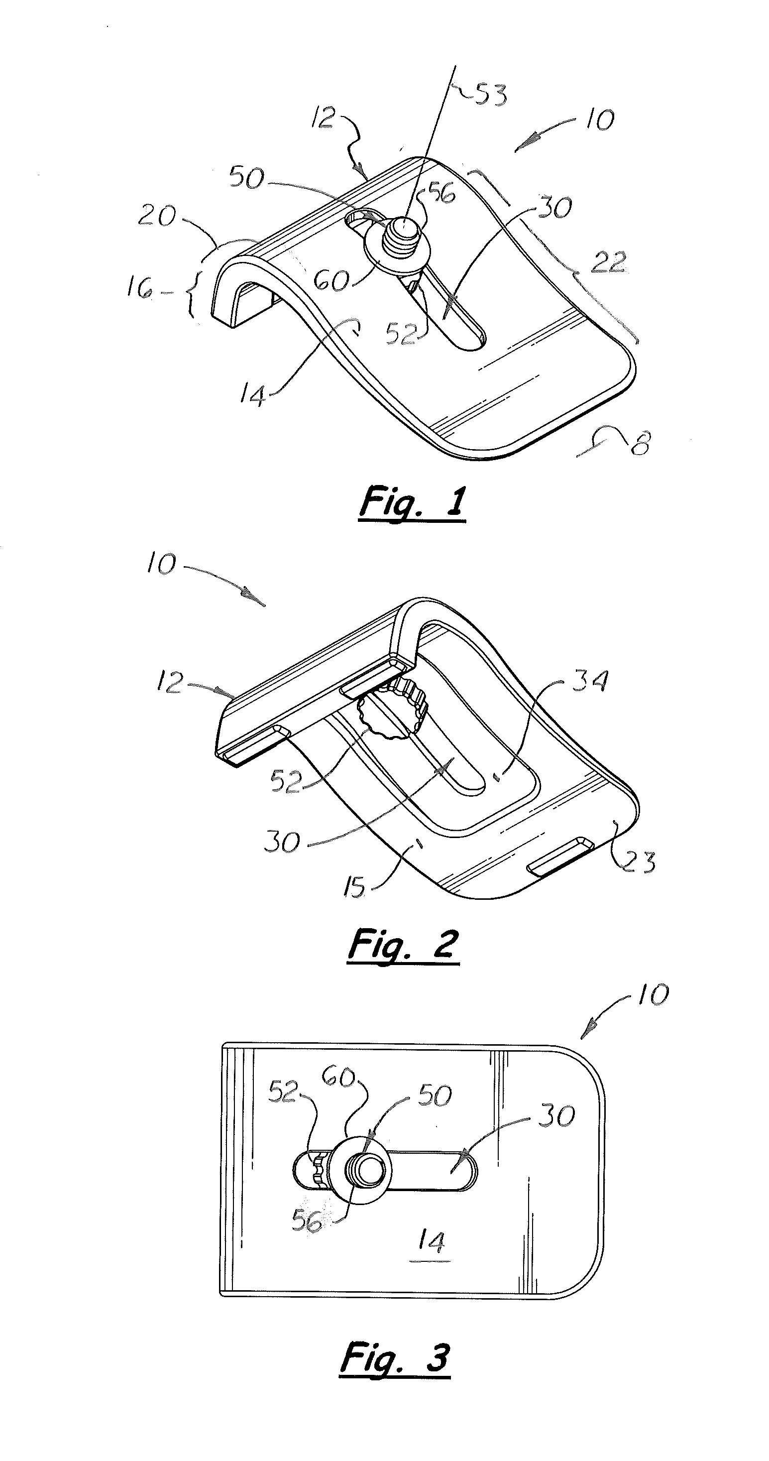
[0051]Referring to the accompanying FIGS. 1-8, a holding apparatus 10 is shown that includes a base 12 with complex curved top surface 14 that has an upward extending short front section 16, an curved intermediate section 20, and a long concave curved rear incline section 22. Formed on the base 12 is a central, longitudinally aligned slot 30 that extends continuously from the convex curved intermediate section 20 and a substantially into the rear inclined section 22. The lateral areas of the top surface 14 adjacent to the slot 30 are relatively straight and aligned thereby enabling the lower surface of an electronic device 200, such as a camera, cell phone, tablet computer or MP3 player to be extended across and supported thereon.

[0052]The holding apparatus 10 also includes an inverted bolt 50 with a head 52 and thread shaft 56. During assembly, the head 52 is positioned against the bottom surface 15 on the base 12 and the shaft 56 is extended through and slides freely along the sl...


PUM

PropertyMeasurementUnit
Angleaaaaaaaaaa
Sizeaaaaaaaaaa
Areaaaaaaaaaaa

Abstract

A holding apparatus that includes a base with complex curved upper surface with an upward extending front arc section, a long curved incline section, and a longitudinally aligned slot formed on the upper surface. The area of the upper surface adjacent to the slot is relatively flat enabling the lower surface of a camera or an device holder disposed transversely over the base to may be perpendicular aligned with base adjacent to the bolt. The bolt is inverted with a head and a threaded shaft that extends through the slot. During assembly, an electronic device may be disposed over the top surface of the base and securely attached to the exposed end of the bolt. By moving the bolt to different positions on the slot, the electronic device may be positioned at different locations on the base and at different angles. The base may be used with an optional device holder or an extension adapter.

Description

[0001]This utility patent application is based upon and claims the filing date benefit of U.S. provisional patent application (Application No. 61 / 726,268) filed on Nov. 14, 2012.[0002]Notice is given that the following patent document contains original material subject to copyright protection. The copyright owner has no objection to the facsimile or digital download reproduction of all or part of the patent document, but otherwise reserves all copyrights.BACKGROUND OF THE INVENTION[0003]1. Field of the Invention[0004]This invention pertains to relatively small apparatuses for temporarily holding an electronic device, such as a camera, cell phone or MP3 player, on a support surface such as a table top that also allows the operator to easily reposition the electronic device when attached to the apparatus for optimal operation and viewing.[0005]2. Description of the Related Art[0006]Tripods with length adjustable legs are commonly used to hold a camera when taking pictures. The legs on...

Claims


Application Information

Patent Timeline
IPC IPC(8): F16M11/04
CPCF16M11/048F16M11/041F16M11/10F16M11/16F16M13/00Y10T29/49947
Inventor CHUN, JAMES K.
Owner CHUN JAMES K
Learn More