
Insufflation needle apparatus

a needle and needle technology, applied in the field of surgical instruments, can solve the problems of increased recovery time for patients, difficult laparoscopic surgery, and considerable trauma

Inactive Publication Date: 2003-12-02
APPL MEDICAL RESOURCES CORP
View PDF31 Cites 70 Cited by
  • Summary
  • Abstract
  • Description
  • Claims
  • Application Information

AI Technical Summary

Benefits of technology

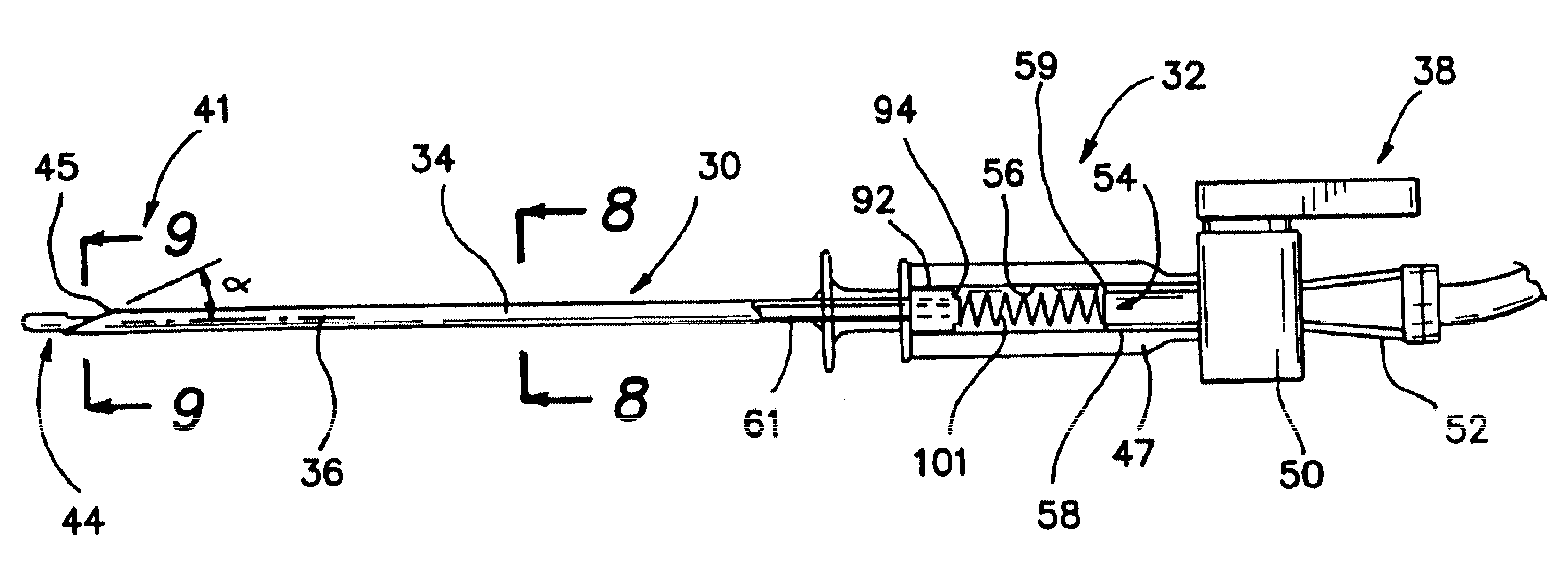
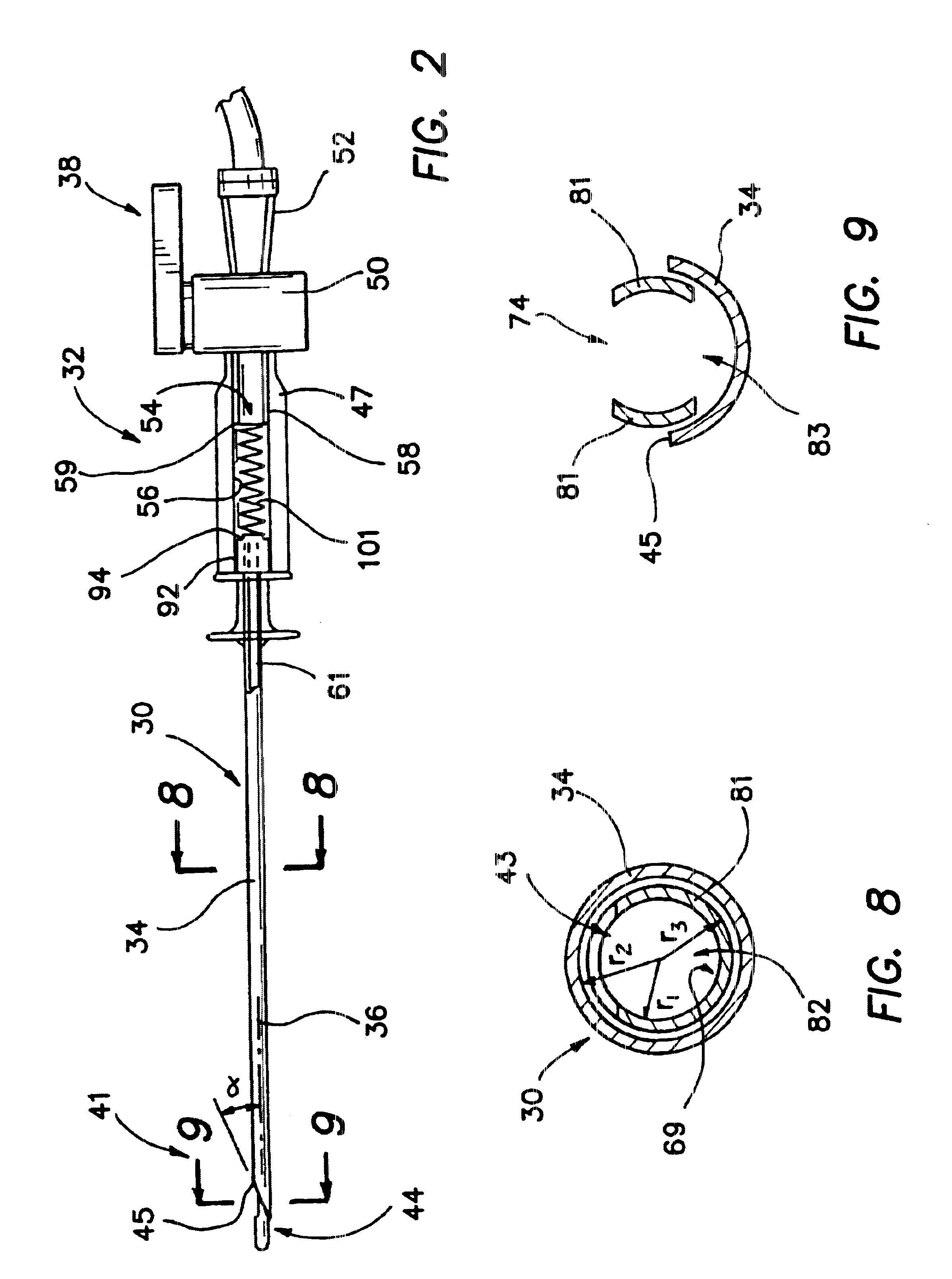
Another aspect of the invention is associated with a method for insufflating a body conduit or cavity. In accordance with this method a needle is provided with a first lumen extending between a proximal end and sharpened distal end. An obturator is inserted into this lumen of the needle. The obturator is provided with a wall defining an insufflation channel and forming at least a portion of a cylinder with an internal radius r.sub.1. By removing portions of this wall, the insufflation channel is provided with a cross-sectional area along the entire length of the channel which is greater than .PI.r.sub.1.sup.2. This area will typically be less than about .PI.[r.sub.2.sup.2 -1 / 2(r.sub.3.sup.2 -r.sub.1.sup.2)] and preferably about .PI.[r.sub.2.sup.2 -2 / 3(r.sub.3.sup.2 -r.sub.1.sup.2)], where r.sub.1 is the inner radius of the obturator wall, r.sub.2 is the radius of the needle lumen, and r.sub.3 is the outer radius of the obturator wall. By removing portions of the wall defining the insufflation channel, the cross-sectional area is increased resulting in an increased insufflation rate. Removing the wall portions also reduces the mass of the obturator resulting in a decreased transition time between the proximal position and the distal position of the obturator.

Problems solved by technology

These open procedures have invited infection, have produced considerable trauma, and have increased recovery time for the patient.
In spite of these advantages, laparoscopic surgeries are difficult to perform since the abdominal cavity is maintained substantially intact.
Not only does this decrease visibility of the operative site, but it also provides a limited volume within which to manipulate instruments.
Of course, the speed of this movement between positions is limited by the mass of the obturator.
Where the transition has not been sufficiently rapid, momentary exposure of the sharpened tip has tended to damage interior organs.
By removing portions of the wall defining the insufflation channel, the cross-sectional area is increased resulting in an increased insufflation rate.

Method used


Image

  • Insufflation needle apparatus
  • Insufflation needle apparatus
  • Insufflation needle apparatus

Examples


Embodiment Construction

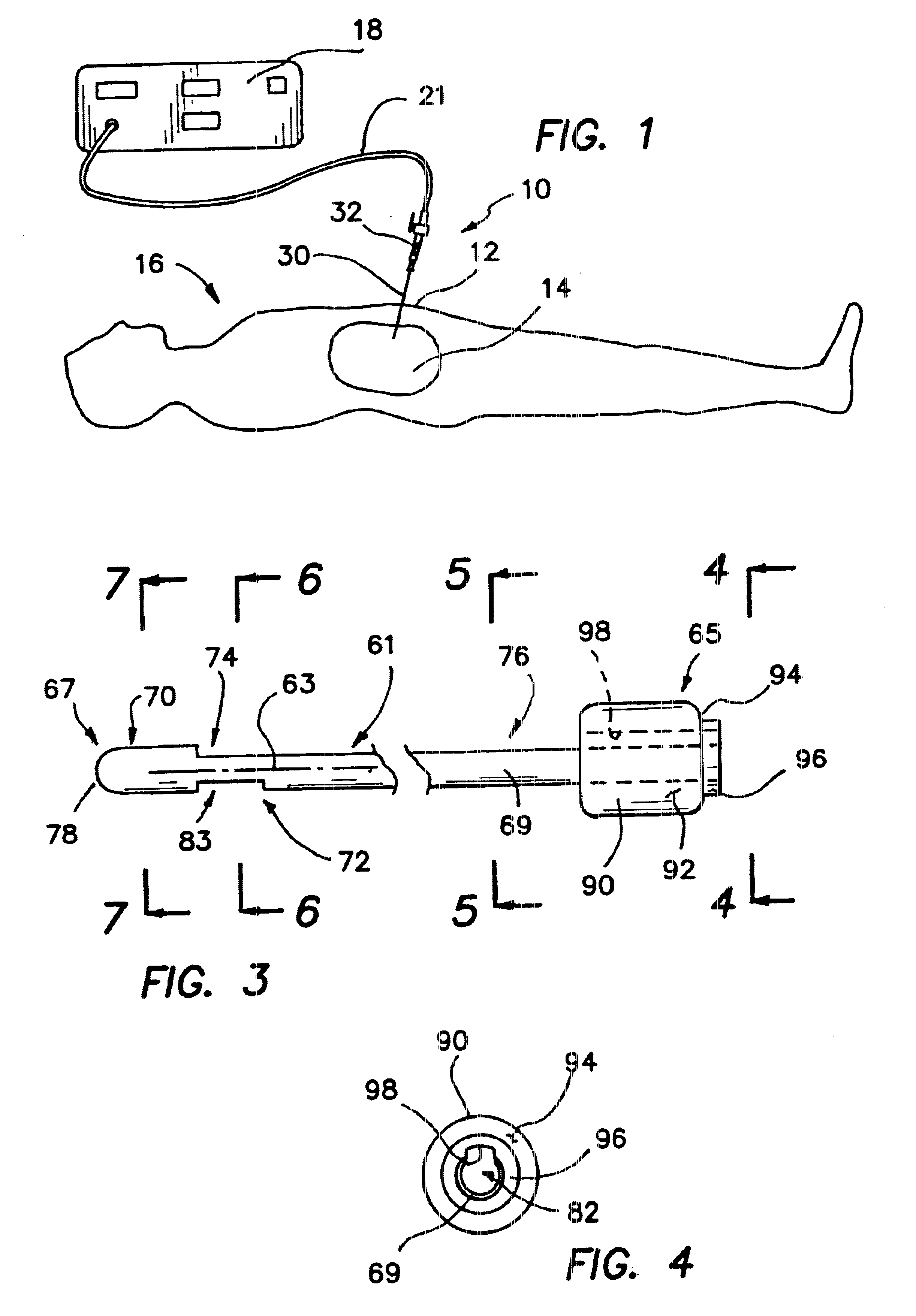
An insufflation needle apparatus is illustrated in FIG. 1 and designated generally by the reference numeral 10. The apparatus 10 is illustrated in operative disposition across an abdominal wall 12 to provide access to an abdominal cavity 14 of a patient 16. Pressurized gas, such as carbon dioxide, from a gas source 18 is introduced through a flexible tube 21 and the insufflation apparatus 10 to pressurize, inflate and distend the abdominal cavity 14 of the patient 16. This enlarges the cavity 14 and thereby facilitates laparoscopic surgeries.

Although the insufflation needle apparatus 10 is particularly adapted for use in laparoscopic procedures, there are other types of surgeries where insufflation gases are used to enlarge various body conduits and other body cavities.

The insufflation needle apparatus 10 includes an elongate needle 30 extending distally from a handle 32 as best illustrated in the enlarged view of FIG. 2. The needle 30 has a generally hollow cylindrical configuratio...


PUM


Abstract

Apparatus for insufflating a body conduit or cavity includes a needle having a lumen defined by an inner surface and a sharp distal tip. An obturator, disposed within the lumen of the needle and movable axially between a proximal position and a distal position, includes an extension member which defines an insufflation channel with the inner surface of the needle. A blunt distal terminus on the extension member is disposed distally of the sharp tip of the needle when the obturator is in the distal position.

Description

1. Field of the InventionThis invention relates generally to surgical apparatus and more specifically to a needle apparatus and method for insufflating a body conduit or cavity.2. Discussion of the Prior ArtIn the past, abdominal surgery has been conducted through large open incisions which provide direct access to the interior regions of the abdomen. These open procedures have invited infection, have produced considerable trauma, and have increased recovery time for the patient.More recently, less invasive procedures have been developed for conducting abdominal surgeries through tubular access devices commonly referred to as trocars. These procedures, which call for the placement of the trocar across the abdominal muscle which defines the abdominal wall, are commonly referred to as laparoscopic procedures. In these delicate operations, small surgical instruments and endoscopes are inserted through working channels of the trocars to perform various surgical functions within the abdo...

Claims


Application Information

Patent Timeline
IPC IPC(8): A61B17/34
CPCA61B17/3496A61B17/3474
Inventor TAYLOR, SCOTTJOHNSON, GARYHILAL, NABIL
Owner APPL MEDICAL RESOURCES CORP
Learn More