
Method and apparatus for circuit fault detection with boiler water level detection system

a detection system and circuit fault technology, applied in liquid/fluent solid measurement, machines/engines, instruments, etc., can solve problems such as rapid overheating of tubes, explosion of boilers, and heat conduction from tubes

Inactive Publication Date: 2003-11-18
TYCO VALVES & CONTROL INC
View PDF13 Cites 26 Cited by
  • Summary
  • Abstract
  • Description
  • Claims
  • Application Information

AI Technical Summary

Benefits of technology

The system effectively identifies open or short circuits and water vs. steam conditions without causing hydrolysis, providing robust and reliable level indications while avoiding the risks associated with direct current components.

Problems solved by technology

The control of water level in a steam boiler is extremely critical, in that if a fire tube is exposed, a boiler explosion could result.
The rate of thermal conductance from a fire tube by water is many times greater than that of steam, thus if steam blankets the tube, there is insufficient heat conduction from the tube and the tube rapidly overheats.
However, boilers typically operate at high temperatures and pressures, often at a normal operating pressure of 3,000 psi.
This factor presents an engineering challenge to make the sight glasses robust in such a hostile environment.
As a consequence, sight glasses often leak, and a small leak at such a high pressure can quickly develop into a serious problem.
However, electronic level indicators present challenges in design all their own due to the high temperatures involved.
The DC potential may cause hydrolysis of the water, and can result in explosive concentrations of hydrogen and oxygen within the steam system or electroplating.
However, the art does not describe a system which includes a dual frequency sensing signal which develops no direct current aspect, and which is used to indicate an open circuit condition, or short circuit condition on the same sense line, as well as boiler level measurements and a fault indicator, all within the same sensing circuit.

Method used


Image

  • Method and apparatus for circuit fault detection with boiler water level detection system
  • Method and apparatus for circuit fault detection with boiler water level detection system

Examples


Embodiment Construction

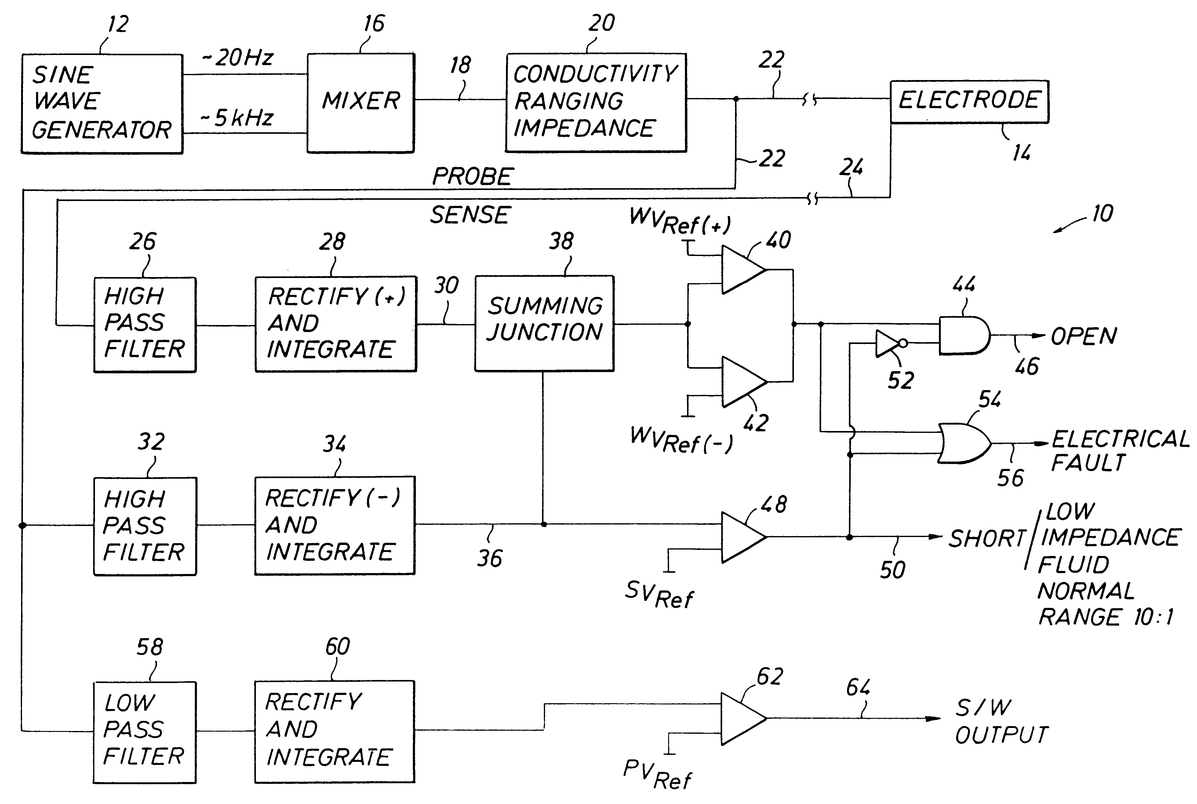
The drawing FIGURE depicts a preferred embodiment of the present invention, wherein a circuit fault detection system 10 is provided. The system 10 begins conceptually with a periodic signal generator 12, preferably a dual frequency sine wave generator. The signal generator 12 provides two frequencies, which are not multiplexed, but rather are superimposed on one another. The lower of the two frequencies, for example about 20 Hz, is used for the measurement of the presence of water or steam at the specific level of an electrode or probe 14 and the higher of the two frequencies, for example about 5 KHz, is used for detection of circuit fault. The lower frequency is used for fluid level detection because water, particularly boiler water with its boiler water chemistry, is not purely resistive, and thus presents a reactive impedance. The reactive impedance of the boiler water would develop erroneous measurements at higher frequencies. The higher frequency of 5 KHz was selected to provid...


PUM


Abstract

A fault detection circuit in a boiler-water level system includes a dual-frequency signal generator which develops two AC components with no associated DC component. The two frequencies are mixed and sent through an impedance matching circuit to match the impedance of the signal generating portion of the system with the impedance of the boiler water under measurement. The impedance-matched signal is then directed to two legs, one leg directed through one of a plurality of electrode probes and then to a first filter circuit, and the other leg is directed a second set of filters. In combination, the filters pass either the higher or the lower of the two frequencies to determine an open or short condition in the level sensing circuitry, as well as a steam vs. water condition.

Description

(1) Field of the InventionThe present invention relates generally to the field of boiler water level detectors and, more particularly to systems for the detection of electrical faults, as well as water versus steam detection, in boiler water level detectors.(2) Description of Related ArtThe control of water level in a steam boiler is extremely critical, in that if a fire tube is exposed, a boiler explosion could result. The rate of thermal conductance from a fire tube by water is many times greater than that of steam, thus if steam blankets the tube, there is insufficient heat conduction from the tube and the tube rapidly overheats. In order to avoid this potentially catastrophic occurrence, steam systems are required to provide redundant water level indicators for each boiler.One common solution to the requirement for redundant water level indicators has for some time included two independent visual level indicators. Such visual level indicators require penetrations for top and bot...

Claims


Application Information

Patent Timeline
Patent Type & Authority Patents(United States)
IPC IPC(8): G01F23/24G01F25/00
CPCG01F25/0076G01F23/244G01F25/24G01F25/00G01F23/24
Inventor SANDERS, GARY G.
Owner TYCO VALVES & CONTROL INC
Learn More