
Fan speed controller with conditioned tachometer signal

a technology of conditioned tachometer and variable speed fan, which is applied in the direction of dynamo-electric converter control, motor/generator/converter stopper, etc., can solve the problems of premature failure and corruption of logic generating tachometer output signals, affecting the robust implementation of variable speed fan controller, and acoustic noise of the fan and the maximum power consumption of the fan

Inactive Publication Date: 2003-11-18
DELL PROD LP
View PDF13 Cites 110 Cited by
  • Summary
  • Abstract
  • Description
  • Claims
  • Application Information

AI Technical Summary

Problems solved by technology

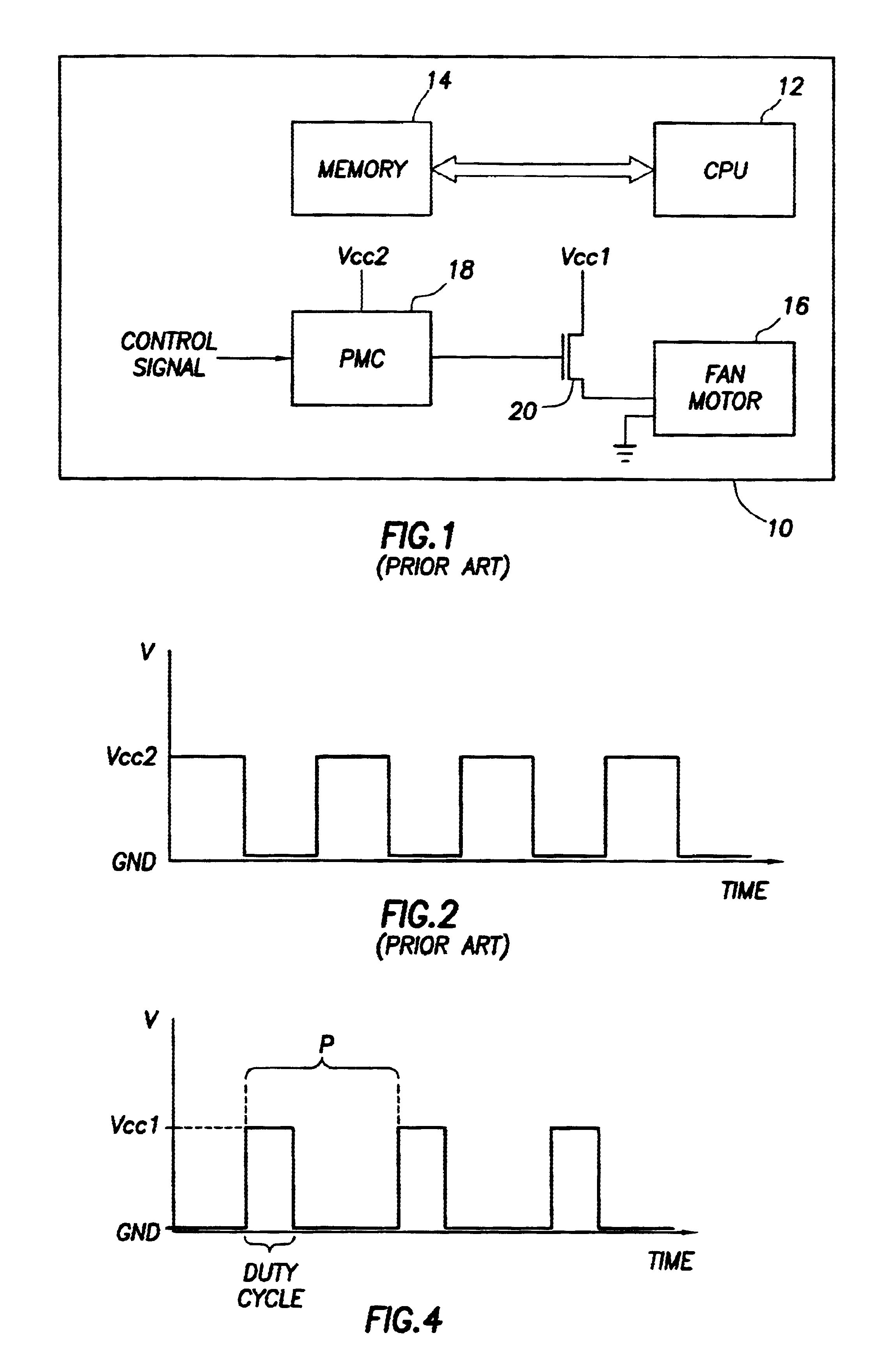
Ideally, maximum airflow (fan fully on) allows for best cooling results, however, acoustical noise from the fan and fan power consumption are also at maximum.
However, robust implementation of a variable speed fan controller is hard to achieve due to different fan manufacturers' requirements for supply voltage stability and available signal quality of fan tachometer (rotational speed) output (especially at low rotational speeds).
This provided desirable results regarding fan noise and power consumption, but in some fans it caused premature failures and corruption of logic generating the tachometer output signals from the fan.
This allowed for seamless fan control, however, if the fan controller IC implemented direct PWM control, then the same fan reliability issues were still present.
A significant drawback of using the fan controller IC was cost.
However, a drawback was requiring dedicated binary outputs and only course resolution for fan speed control (e.g., most often there are only three fan speed settings: OFF, LOW, HIGH).
Heretofore, low fan speeds could not be utilized below a certain voltage because the fan digital circuits for producing a rotational speed tachometer output were failing to produce acceptable logical levels due to the low supply voltage to the fan motor.
In other words, the supply voltage would be sufficient to run the fan at a low speed but the tachometer output became non-functional at low speeds corresponding to the low voltages.
Inaccurate tachometer signals will create undesirable and unreliable control of the fan motor 16 when running at low speeds.
When the fan supply voltage is brought to a value necessary to obtain the minimum possible fan speed without allowing it to stall, in some fans the tachometer output signal quality will significantly deteriorate and the tachometer output signal will not be recognizable by conventional PMC systems.

Method used


Image

  • Fan speed controller with conditioned tachometer signal
  • Fan speed controller with conditioned tachometer signal
  • Fan speed controller with conditioned tachometer signal

Examples


Embodiment Construction

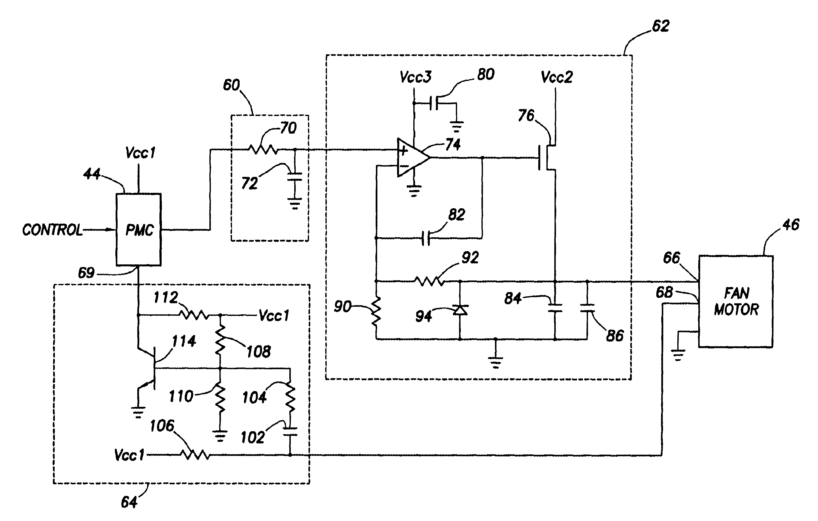
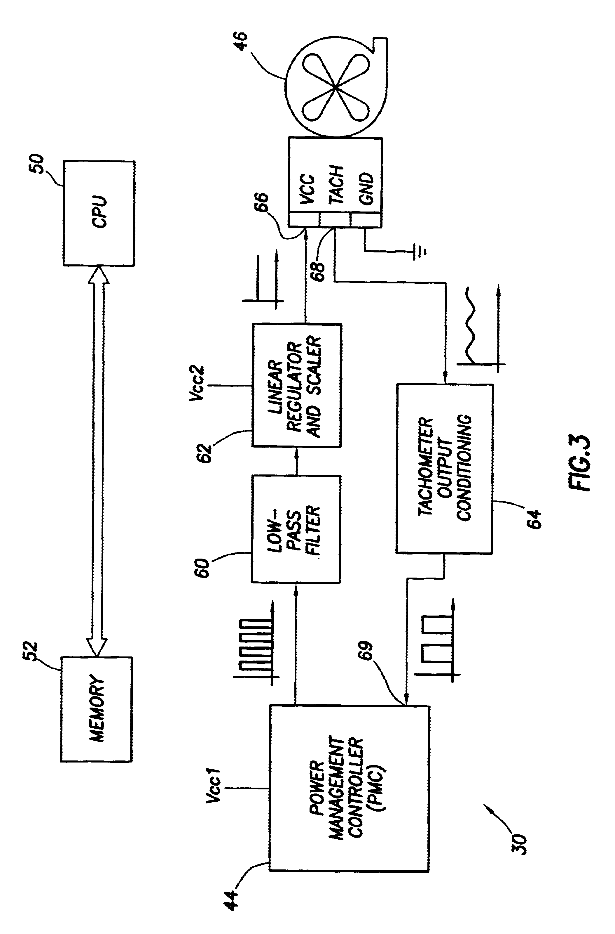
The present invention is directed to fan speed control with a conditioned tachometer signal in an information handling system. Use of a standard power management control circuit and inexpensive components enables continuous fan speed control and monitoring with a minimum of input-output ports, and these ports may be standard digital ports.

Disclosed is a circuit for controlling a DC voltage in response to receiving a square wave signal having a varying duty cycle, e.g., pulse width modulation (PWM). Control of the magnitude of the DC voltage varies according to the duty cycle of the received square wave signal. The DC voltage may be provided to an input node of a electrical or electronic device. For purposes of explanation, the present invention will be described with reference to a circuit for providing a DC voltage to a power-input node of a fan motor contained within an information handling system, it being understood that the present invention should not be limited thereto.

For pu...


PUM


Abstract

The speed of a fan motor is controlled by varying a DC voltage to the fan motor. A series pass transistor is used to vary the DC voltage to the fan motor. A power management controller sets the fan motor speed by outputting pulses to a pulse-to-DC voltage converter that changes the pulses to a proportional DC control voltage for controlling the series pass transistor. A tachometer output amplifier circuit is used to remove DC components and amplify to useful logic levels a low level tachometer output signal from the fan motor. The amplified tachometer signal is used by the power management controller in controlling the rotational speed of the fan motor.

Description

BACKGROUND OF THE INVENTION TECHNOLOGY1. Field of the InventionThe present application is related to information handling systems, and more specifically, to information handling systems having variable speed cooling fans.2. Description of the Related ArtInformation handling systems play a vital role in modern society. An information handling system generally processes, compiles, stores, and / or communicates information or data for business, personal or other purposes, thereby allowing users to take advantage of the value of the information. Because technology and information handling needs and requirements vary between different users or applications, information handling systems may also vary regarding what information is handled, how the information is handled, how much information is processed, stored, or communicated, and how quickly and efficiently the information may be processed, stored, or communicated.The variations in information handling systems allow for these systems to ...

Claims


Application Information

Patent Timeline
IPC IPC(8): G06F1/20H02P7/288H02P7/18
CPCG06F1/206H05K7/2019H02P7/288Y02B60/1275Y02D10/00
Inventor VYSSOTSKI, NIKOLAICRITZ, CHRISTIAN L.
Owner DELL PROD LP
Learn More