
Liquid containment/diversion dike

a technology of liquid containment and diversion dike, which is applied in the direction of dams, dykes, marine site engineering, etc., can solve the problems of difficulty in removing the barrier of sand bags when it is no longer, the cost of producing sandbags, etc., and achieves low cost, low cost, and strength and integrity. , the effect of increasing the strength

Inactive Publication Date: 2003-11-04
FLOOD SERVICES +1
View PDF33 Cites 90 Cited by
  • Summary
  • Abstract
  • Description
  • Claims
  • Application Information

AI Technical Summary

Benefits of technology

A liquid-fillable liquid containment / diversion dike has been invented which can be used to contain or divert a flow of liquid such as a flood or a liquid chemical spill. The dike is easily transported and is tillable on site. When the dike is no longer required, it can be emptied of the liquid it contains and then transported to the next site where it is required. The dike is resistant to failure due to puncture because of a multiple bladder arrangement.
Sealable ports are provided in each separate bladder to provide for access to the interior of the bladder for filling. Preferably, a one-way valve is provided at each port for connection to an injection nozzle. In a preferred embodiment, a header device is provided having a plurality of connectors for simultaneous connection to a plurality of bladder valves. Such a header device provides that more than one bladder can be filled simultaneously. Preferably, all valves are positioned on the side wall of the bladder or on the end wall of the bladder proximal to a side of the bladder to facilitate filling of the bladder without collapse. To prevent overfilling, preferably a check valve is provided in a wall of the bladder. In one embodiment, a pressure transducer is positioned in communication with the interior of at least some of the bladders of the dike section so that an alarm will sound if the pressure in a bladder falls below a predetermined level.
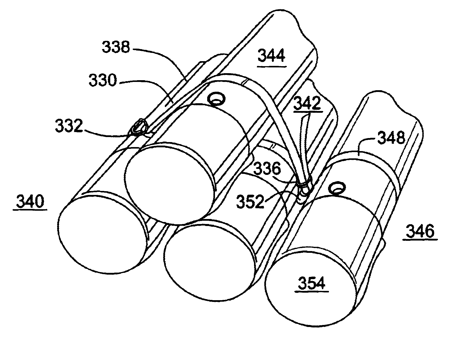
It has been found that the operation of the dike section can be enhanced by preventing the water from seeping between the bladders. Thus, in one embodiment, a sheet of material can be partially or fully wrapped about the dike section at the intersection of abutting dike sections or along the length of a dike section. In addition, or alternately, a sheet of material is positioned over the containment side of the dike section to extend a selected distance over the ground surface away from the dike section. The sheet of material is preferably liquid-tight.
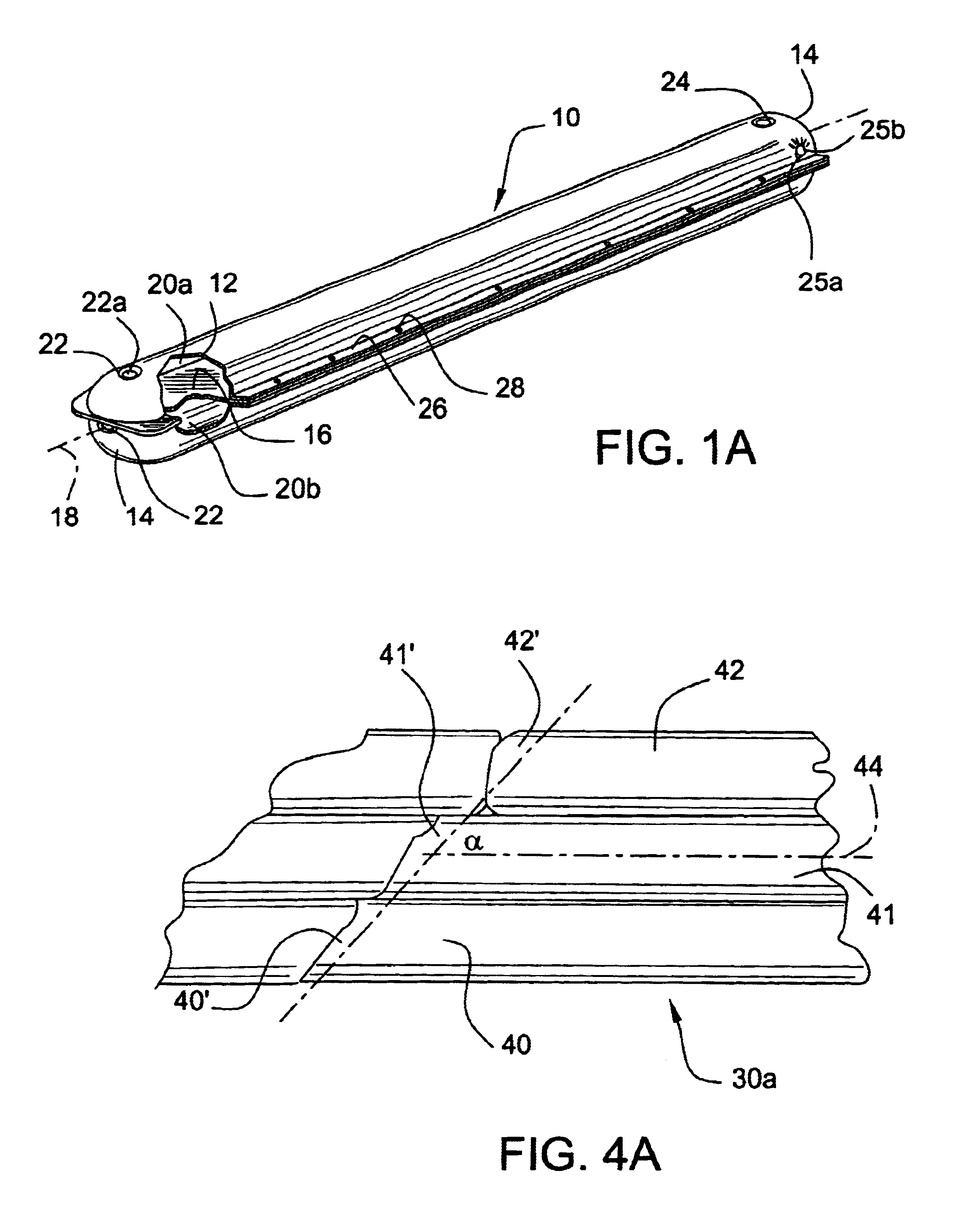
According to another feature of the present invention, the bladder is formed as tube and the open ends are heat sealed or welded. To provide additional strength and integrity to the bladder ends, at least one of the ends is folded back on the bladder and maintained in this configuration by an end reinforcing sleeve. Thus, the ends do not independently withstand the pressure of the liquid within the bladder but instead are reinforced beneath the sleeve. Such a bladder is producible at low costs since a tube of watertight material can be used and cut into any suitable length and heat sealed or welded. Low cost welding procedures have been found to be particularly appropriate and cost efficient to close off the ends of the tubes.

Problems solved by technology

Sandbagging to divert liquid flow has certain disadvantages including the cost of producing the sandbags and the difficulty in removing the barrier of sand bags when it is no longer required.

Method used


Image

  • Liquid containment/diversion dike
  • Liquid containment/diversion dike
  • Liquid containment/diversion dike

Examples


Embodiment Construction

, briefly described above, will follow by reference to the following drawings of specific embodiments of the invention. These drawings depict only typical embodiments of the invention and are therefore not to be considered limiting of its scope. In the drawings:

FIG. 1A is a perspective view of a dike bladder according to teachings of the present invention, the end of the dike bladder being cut away to show the internal structure;

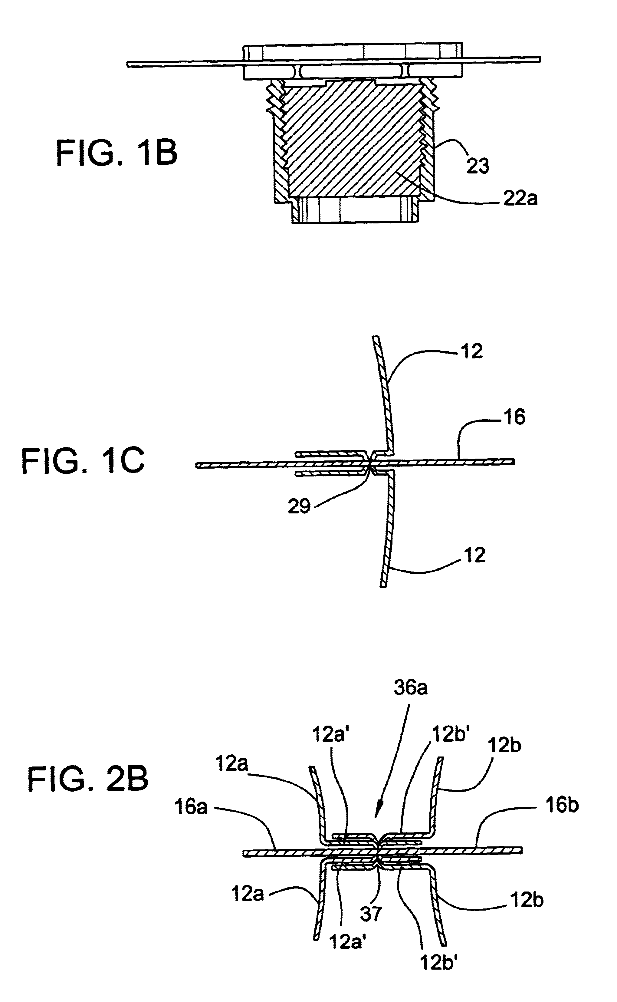
FIG. 1B is a sectional view through a bladder plug useful in the present invention;

FIG. 1C is a sectional view through a bladder side seam useful in the present invention;

FIG. 1D is a perspective view of an end of a dike bladder according to teachings of the present invention;

FIG. 1E is a side elevation view of another bladder according to teachings of the present invention shown partly in section;

FIG. 2A is a perspective view of dike section according to teachings of the present invention, the end of the dike section being cut away to show the internal stru...


PUM


Abstract

A liquid filled dike is described. The dike is formed of a flexible material selected to contain water. The dike includes at least two bladders which extend at least a portion of the length of the dike. The dike can be transported in empty condition and filled on site. When it is no longer required at a particular site, the dike can be emptied and stored for later use. The dike is self-leveling and may include a leak detection system.

Description

This invention is directed to a liquid containment / diversion dike and, in particular a liquid-fillable containment / diversion dike for flood control or liquid containment, bladder elements for use in the dike and a method for construction of a liquid containment / diversion dike.Many systems have been employed for controlling the spread of flood waters or fluid spills. One of the most common means for containing or diverting a flow of liquid is sandbagging wherein bags are filled with sand and piled to form a dike. Sandbagging to divert liquid flow has certain disadvantages including the cost of producing the sandbags and the difficulty in removing the barrier of sand bags when it is no longer required. SUMMARY OF THE INVENTIONA liquid-fillable liquid containment / diversion dike has been invented which can be used to contain or divert a flow of liquid such as a flood or a liquid chemical spill. The dike is easily transported and is tillable on site. When the dike is no longer required, ...

Claims


Application Information

Patent Timeline
Patent Type & Authority Patents(United States)
IPC IPC(8): E02B3/10
CPCE02B3/108Y02A10/11
Inventor CLEMENT, GERALD M.
Owner FLOOD SERVICES
Learn More