
Counter for presenting and/or selling goods

a counter and goods technology, applied in the field of counters, can solve the problems of affecting the pleasant appearance of the counter, requiring a considerable force expenditure, and unable to provide gas springs,

Inactive Publication Date: 2003-10-21
VIELER INT GMBH & CO KG
View PDF14 Cites 15 Cited by
  • Summary
  • Abstract
  • Description
  • Claims
  • Application Information

AI Technical Summary

Benefits of technology

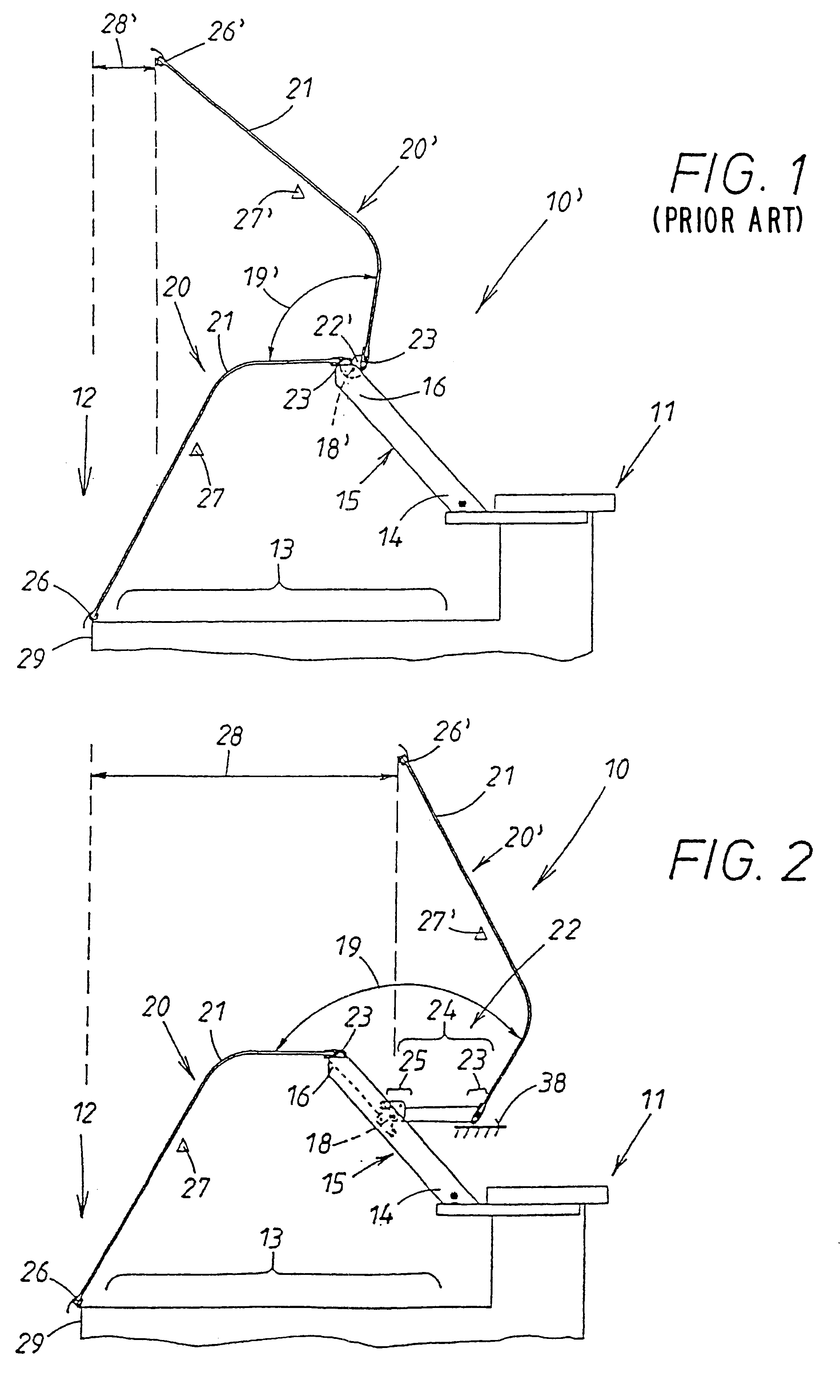
Inasmuch as, the pivotable modular unit is a structure that is rigid within itself, according to the invention a substantially greater pivot angle between the open position and the closed position is also obtained as a result of the arm extending the joint member. In the open position, the free end of the glass pane is pivoted away to such an extent that the support surface of the body of the counter is entirely exposed and especially easily accessible.
Such a requirement can be, in particular, to transfer the free edge of a curved glass pane, which is referred to as a "panoramic pane", in the open position into a position where it extending shortly above the supports and is substantially horizontal. In this connection, the edge of the glass pane is also a so-called "spit protection" for the goods that are present on the support surface of the body of the counter. This is, in particular, suitable when employing the counter for self-service by customers where the customers themselves can remove the goods from the counter. The edge of the glass pane then acts as a roof which partially covers the support surface of the counter. In the open position the counter according to the invention has an especially pleasing appearance; it has an elegant appearance in comparison to counters with a rigid modular unit frame. As a result of the rotary axis between the two partial modular units the glass pane can rotate back upon pivoting.in the counter direction. The free end of the glass pane in this open position does not reach extremely high positions. Accordingly, the rooms where such a counter according to the invention is positioned does not require a high ceiling. Moreover, gripping the free edge of the glass pane, positioned in the open position, of the counter according to the invention is comfortably possible for the purpose of moving the modular unit back into the closed position.

Problems solved by technology

The movement of the center of gravity during opening and closing of the glass pane requires a considerable force expenditure, in particular, during acceleration at the beginning of the pivot movement as well as during braking at the end of the pivot movement.
To provide them in the form of gas springs would be difficult in the case of the known parallelogram linkages.
They would be space-consuming and would impair the pleasant appearance of the counter.

Method used


Image

  • Counter for presenting and/or selling goods
  • Counter for presenting and/or selling goods
  • Counter for presenting and/or selling goods

Examples


third embodiment

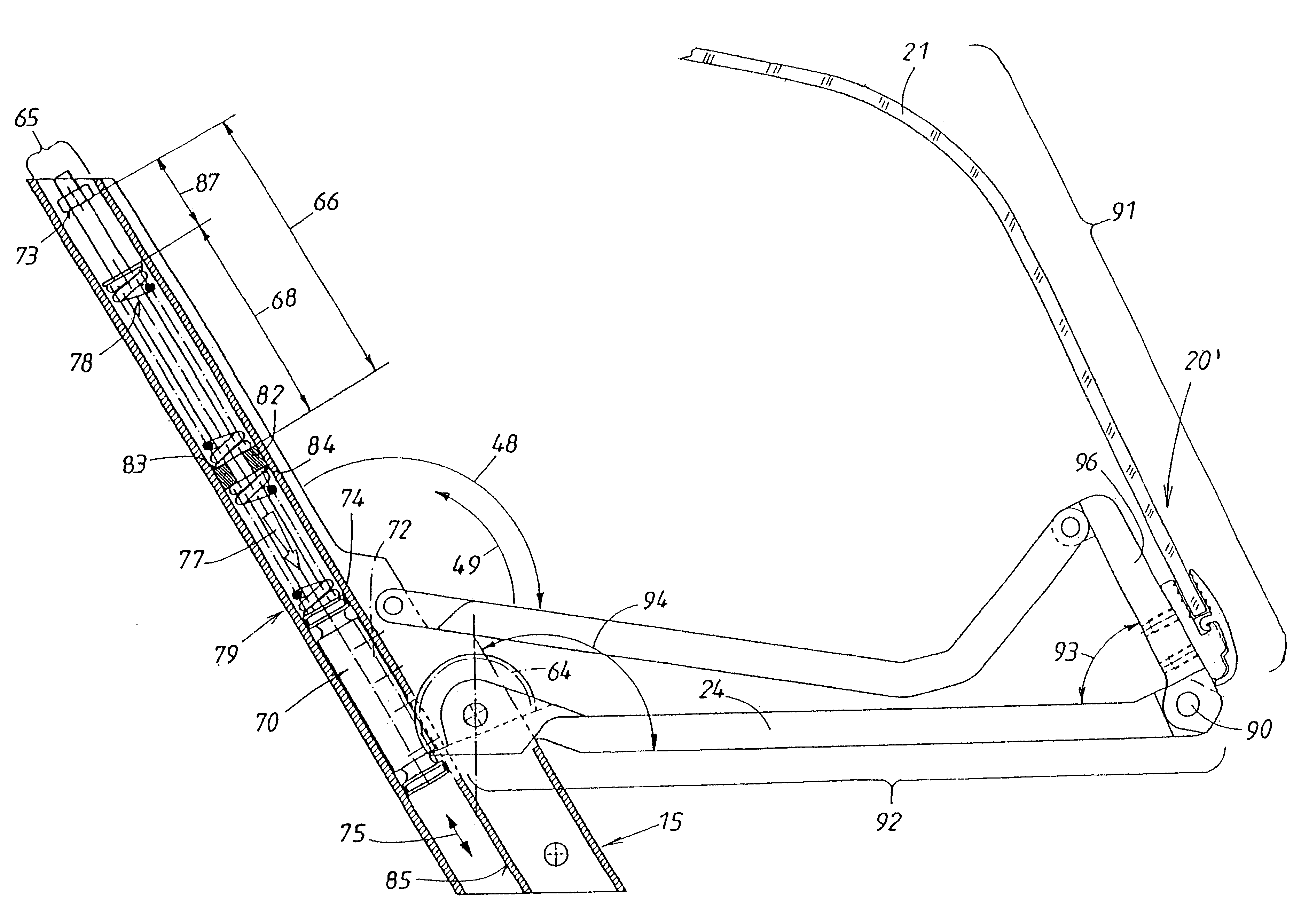
The control member of the third embodiment is comprised of a push member 70 which is longitudinally movable in the sense of double arrow 75. The push member 70 is longitudinally guided in a partial profile 65 of the support 15 and is force-loaded according to the force arrows 76, 77 illustrated in FIGS. 11 and 14. This is realized by two independent forces of which one force load 76 acts in the direction of the closed position 20 and the other 77 in the direction of the open position 20' of the respective modular unit. The two forces 76, 77 act in opposite directions onto the push member 70.

These forces 76, 77 generate two force storage device 78, 79 which are comprised of two coil-shaped pressure springs in this configuration. The push member 70 is divided into two sections 71, 72, i.e., a rod part 71 and a toothed rack support 72. The rod part 71 penetrates the interior of the coil of the two pressure springs 78, 79. The push member 70 has two stops 73, 74 which can be entrained a...

second embodiment

The guide member 80 could also be embodied in a different way. It could be comprised of at least one pair of telescopic members which make it thus longitudinally movable. These telescopic members can be force-loaded in the insertion direction or in the extension direction. This force load can be additive to the afore described force load 76, 77 of the slide 70 or can replace it completely or partially. The free ends of the members of such guide member are connected analogously, on the one hand, to the partial modular unit 91 of the glass pane and, on the other hand, on the body 11 of the counter or on its supports 15 and are moveably supported thereat as in the second embodiment at 44, 77.


PUM


Abstract

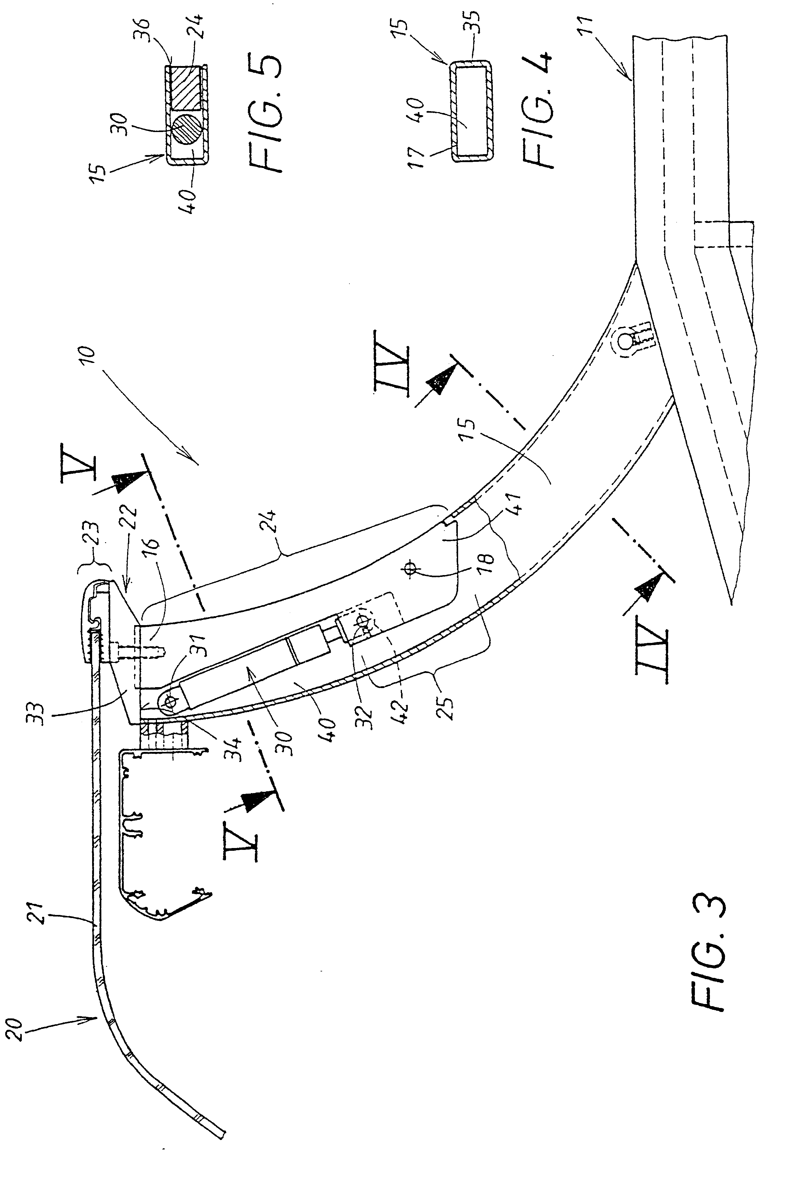
The invention relates to a counter (10) for presenting and / or selling goods. The aim of the invention is to provide a means of displacing a module consisting of a system of joint mechanisms (22) which are associated with a glass pane (21) by means of fixing elements (23) between a closed position (20) in which the inside of the counter (13) is covered and an open position (20') in which it is exposed. Said joint mechanisms (22) are mounted on the supports (15) of the counter (10) in such a way that they can pivot about a horizontal pin (18). In order to ensure that the modular unit is secure in the open position (20') the joint mechanism (22) is provided with an extended arm (24) which has the swivel bearing (18) on its lower arm section. During the transition from the closed position (20) to the open position (20'), the center of gravity (27) of the module in relation to the swivel pin (18) moves to the opposite side (27'). In the closed position (20), the pane (21) is subjected to a torque which acts in the closing direction. In the open position (20'), a torque acts on the pane (21) in the opening direction. The pane (2) can no longer fall back out of the open position (20') into the closed position (20) uncontrollably.

Description

1. Field of the InventionThe invention relates to a counter. The body of the counter has a support surface on which goods are displayed which, on the side facing the customer, are usually covered by a glass pane. Within the body of the counter the lower ends of supports are fastened. Above the body of the counter, a glass pane is provided which can be pivoted about a horizontal axis between a closed position covering the goods on the support surface of the body of the counter, on the one hand, and an open position allowing access to the goods, on the other hand. Joint members are connected by means of a pivot bearing with the support and project at the support end where they have securing means for a glass pane. The joint members with the glass pane fastened on its securing means form a modular unit which is pivotable about a horizontal axis defined by the pivot bearings between a closed position covering the goods on the support surface and an open position allowing access to the g...

Claims


Application Information

Patent Timeline
IPC IPC(8): A47F3/00E05F1/10E05F1/00A47F5/16A47F5/025A47F5/10A47F7/00
CPCA47F3/007E05F1/1091A47F2003/008E05Y2900/204E05Y2201/416
Inventor HACKENBERG, DIETER
Owner VIELER INT GMBH & CO KG
Learn More