
Method and device for detecting specific states of movement of a user

a technology of specific state and user, applied in the direction of static indicating devices, instruments, sport apparatus, etc., can solve the problems of unsatisfactory solutions, less than two degrees of freedom of movement of known devices, and more likely to suffer from virtual reality impression

Inactive Publication Date: 2003-09-23
ITHACA VENTURES K S
View PDF20 Cites 74 Cited by
  • Summary
  • Abstract
  • Description
  • Claims
  • Application Information

AI Technical Summary

Benefits of technology

The user generally stands on the CYBERSURFER, so that he does not in fact have to move from a spot in real space in order to control his locomotion in virtual space. This is important in so far as--because he takes in his entire field of vision through the cyber-helmet--the user is blind to his real environment and therefore could not move safely in the latter. However the device according to the invention can in effect reinforce the user's impression of virtual reality without endangering his safety in the process.
The invention also provides for a method of simulating an activity of a user which includes at least partially supporting the user on a support surface of a support plate which is rotatable relative to a base structure, detecting movements of the support plate by way of a sensor device mounted to the base structure, resisting rotational movement of the support plate relative to an intermediate plate by way of an adjustable rotation biasing device disposed between the support plate and the intermediate plate, resisting a tilting of the support plate by way of a detent device, resisting tilting of the support plate by way of an adjustable tilt restoring device disposed between the base structure and the intermediate plate, and placing the user on the support surface, wherein the support part is rotatable and tiltable about an axis when the user is placed on the support surface.

Problems solved by technology

The impression of virtual reality is more likely to suffer if locomotion in this virtual space cannot be controlled by corresponding real movements of the legs and of the body of the user.
Particularly unsatisfactory solutions are those which employ so-called cyber-gloves to detect hand or arm movements in order to control not just manual actions in virtual space, but also locomotion in this virtual space by, for example, indicating the desired direction.
However this known device is restricted to detecting two degrees of freedom of movement, for example direction and magnitude of the shift of the center of gravity.

Method used


Image

  • Method and device for detecting specific states of movement of a user
  • Method and device for detecting specific states of movement of a user
  • Method and device for detecting specific states of movement of a user

Examples


Embodiment Construction

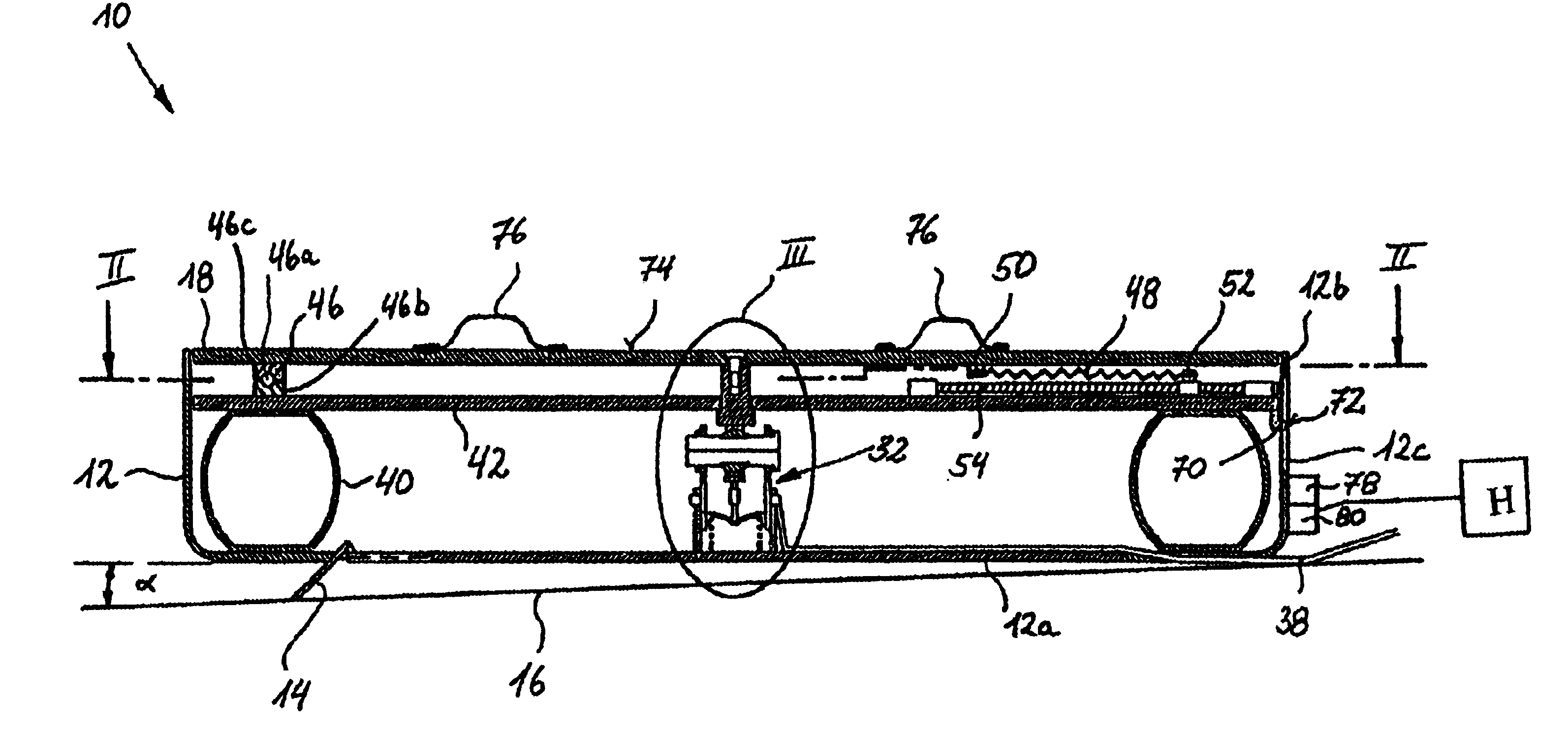
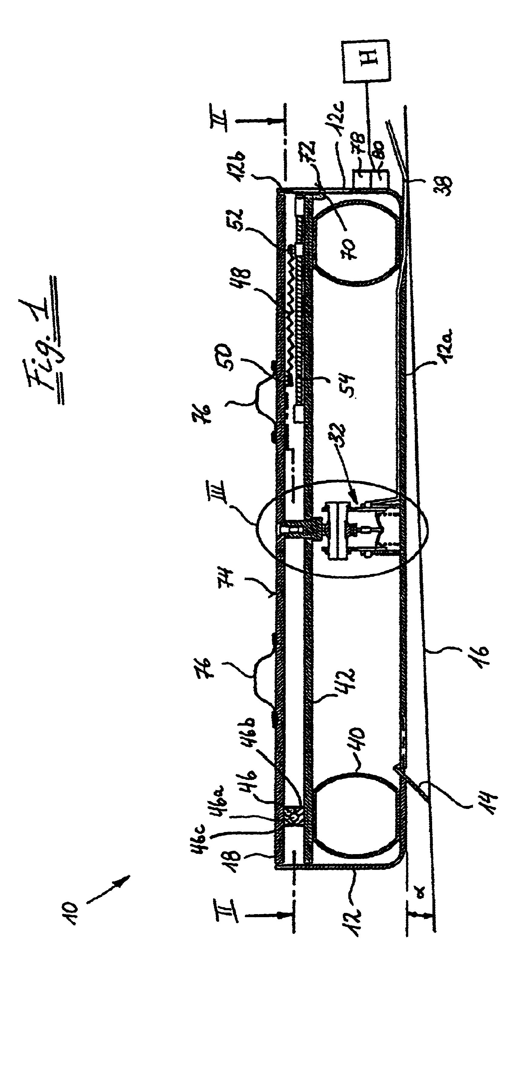
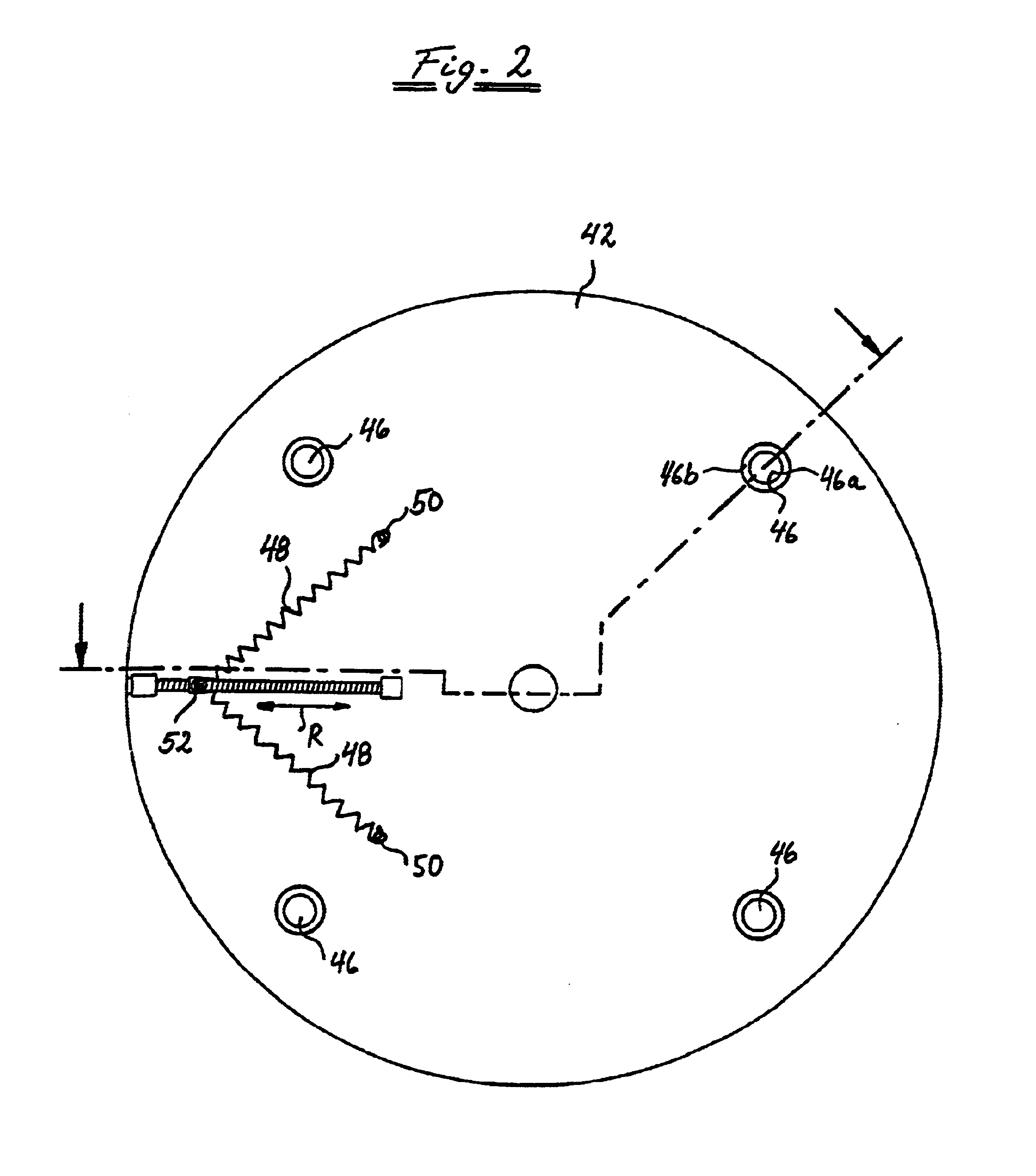
The device according to the invention for detecting certain states of movement of the body of a user is generally designated by 10 in FIG. 1. It comprises a base cradle 12 with a base plate 12a and a circumferential edge adjoining the base plate 12a. The device 10 (also called CYBERSURFER 10 in short in the following) is mounted on the foundation 16, for example a floor of a room, by a swing-out or, in the representation according to FIG. 1, swung-out foot 14. A standing plate 18 is mounted in the base cradle 12.

A pivot pin 22 is secured to the standing plate 18, for example by a screw bolt 20 (see FIG. 3), at the free end of which pin a joint ball 24 is disposed. The joint ball 24 is held in a bearing shell formed by two bearing shell halves 26. The two bearing shell halves 26 are firmly connected together and to a tubular section 28, which is telescopically guided in a further tubular section 30 secured to the base plate 12.

The mounting arrangement illustrated above enables the st...


PUM


Abstract

Process and device for producing input data for a data processing system in which a user stands, sits, kneels, etc. with his entire body on a support plate of a bearing device, such that this support plate is mounted on a base plate which can tilt and / or turn and / or move in the vertical direction. The movements of the support plate according to these degrees of freedom of movement are controlled by the user through the latter shifting his body weight, exerting torques, jumping, etc. A sensor device detects the movements of the support plate and generates corresponding sensor signals, which are fed to the data processing system.

Description

1. Field of the InventionThe invention relates to a device for detecting certain states of movement of the body of a user and for generating signals corresponding to the result of the detection for subsequent processing in a data processing system, and utilizes a bearing device for the body of the user, which device includes a support unit which is mounted in a tiltable manner on a base part and has a support surface for supporting the body of the user, and a sensor device for detecting the direction and the magnitude of the position of the projection of the body's center of gravity into the support surface relative to a predetermined original position in the support surface from the direction and the magnitude of a tilt of the support surface and for generating corresponding sensor signals.2. Discussion of Background InformationGenerally known devices for detecting certain states of movement of a user are designed to be operated by hand (e.g. mouse, joystick or trackball) or by foo...

Claims


Application Information

Patent Timeline
Patent Type & Authority Patents(United States)
IPC IPC(8): A63F9/00G09G5/00G06K11/00G06F3/033G06F3/00
CPCA63F13/06A63F2300/1043A63F2300/1068A63F13/20A63F13/214A63F13/24A63F13/218
Inventor KLEIN, MAXIMILIANLUTZ, PETER
Owner ITHACA VENTURES K S
Learn More