
Automated bicycle steering lock

a bicycle and automatic technology, applied in the direction of steering devices, anti-theft cycle devices, cycle equipments, etc., can solve the problems of not possessing the stamina and endurance to travel as far or as fast as an accompanying adult, and achieve the effect of cost-effective manufacture and simple construction

Inactive Publication Date: 2003-09-23
NELSON EDWARD SCOTT
View PDF9 Cites 20 Cited by
  • Summary
  • Abstract
  • Description
  • Claims
  • Application Information

AI Technical Summary

Benefits of technology

The primary object of this invention is to provide a solid connection between the distal end of a bicycle tow bar and the head tube of a child's bicycle, while also preventing rotation of the steering fork tube and the handlebar stem tube on the child's bicycle during tandem travel. It is a further object of this invention to provide a means of connection between the distal end of a bicycle tow bar and the head tube of a child's bicycle that can be accomplished in one quick, efficient connection step, requires no hand tools, and does not involve the removal of any parts from either bicycle. It is also an object of this invention to provide a means of connection between the distal end of a bicycle tow bar and the head tube of a child's bicycle that is simple in construction for cost-effective manufacture and case of use. A further object of this invention is to provide a means of connection between the distal end of a bicycle tow bar and the head tube of a child's bicycle that is made from durable materials for long-lasting use. It is also an object of this invention to provide a means of connection between the distal end of a bicycle tow bar and the head tube of a child's bicycle that is adaptable to installation during manufacture of the child's bicycle, as well as after-market installation.

Problems solved by technology

However, problems occur with older children, typically ages 4-7, who want the independence of riding their own bicycle, yet do not possess the stamina and endurance to travel as far or as fast as an accompanying adult.

Method used


Image

  • Automated bicycle steering lock
  • Automated bicycle steering lock
  • Automated bicycle steering lock

Examples


Embodiment Construction

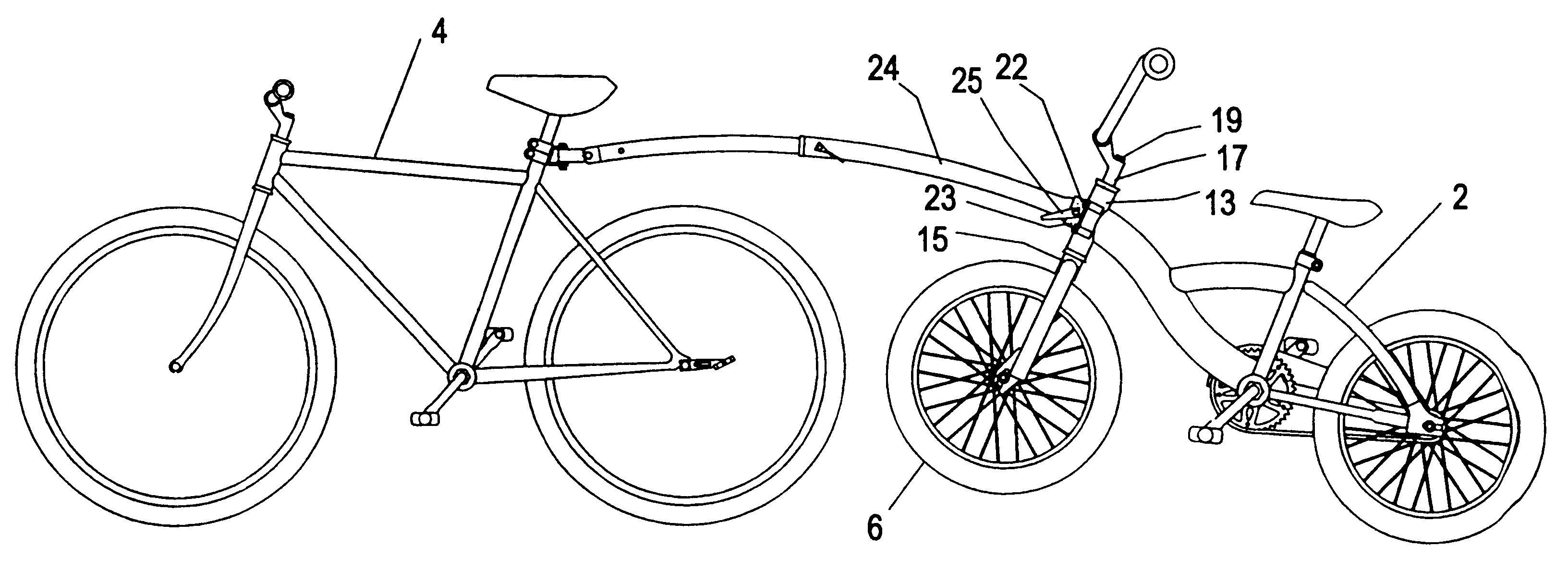
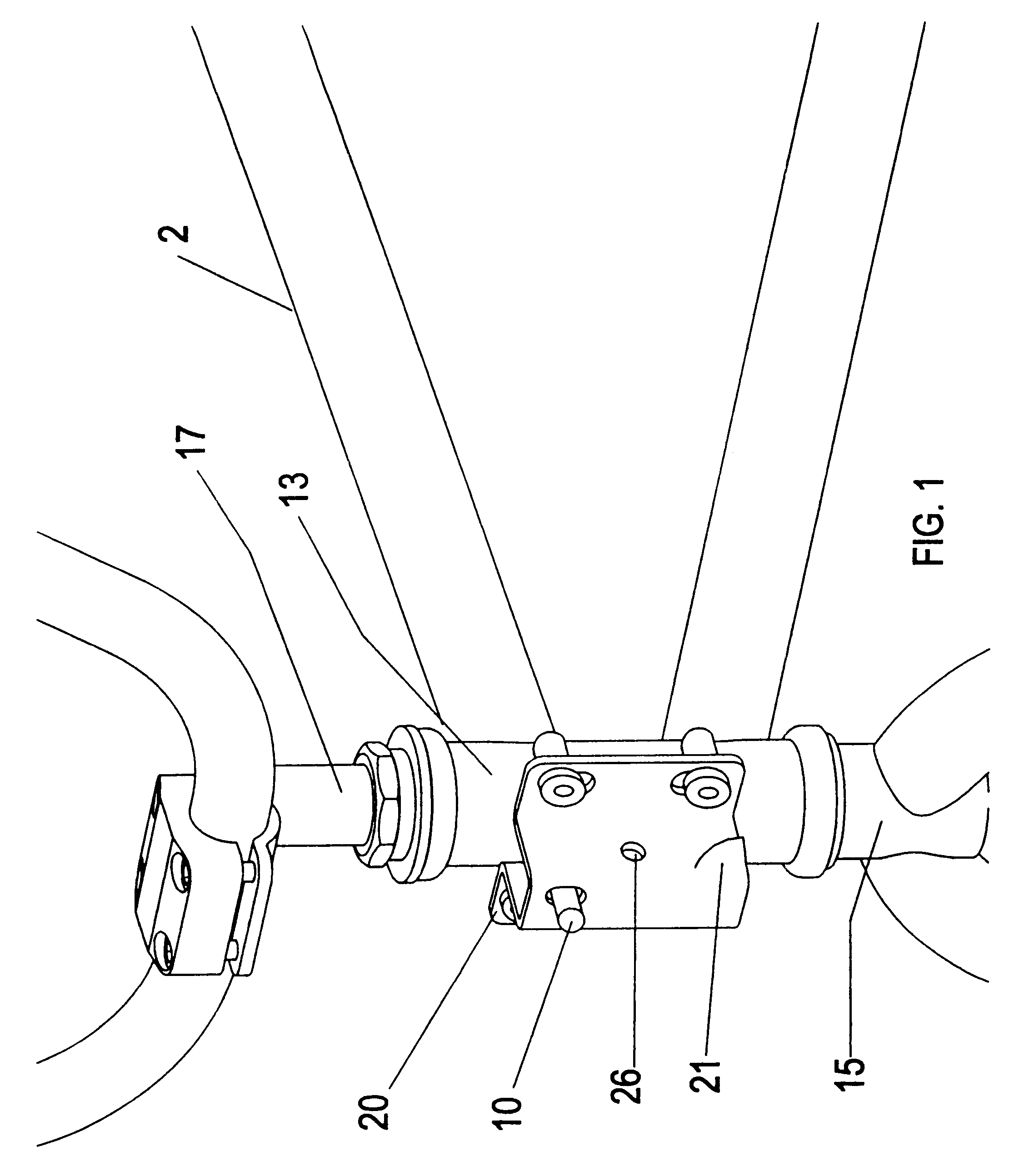
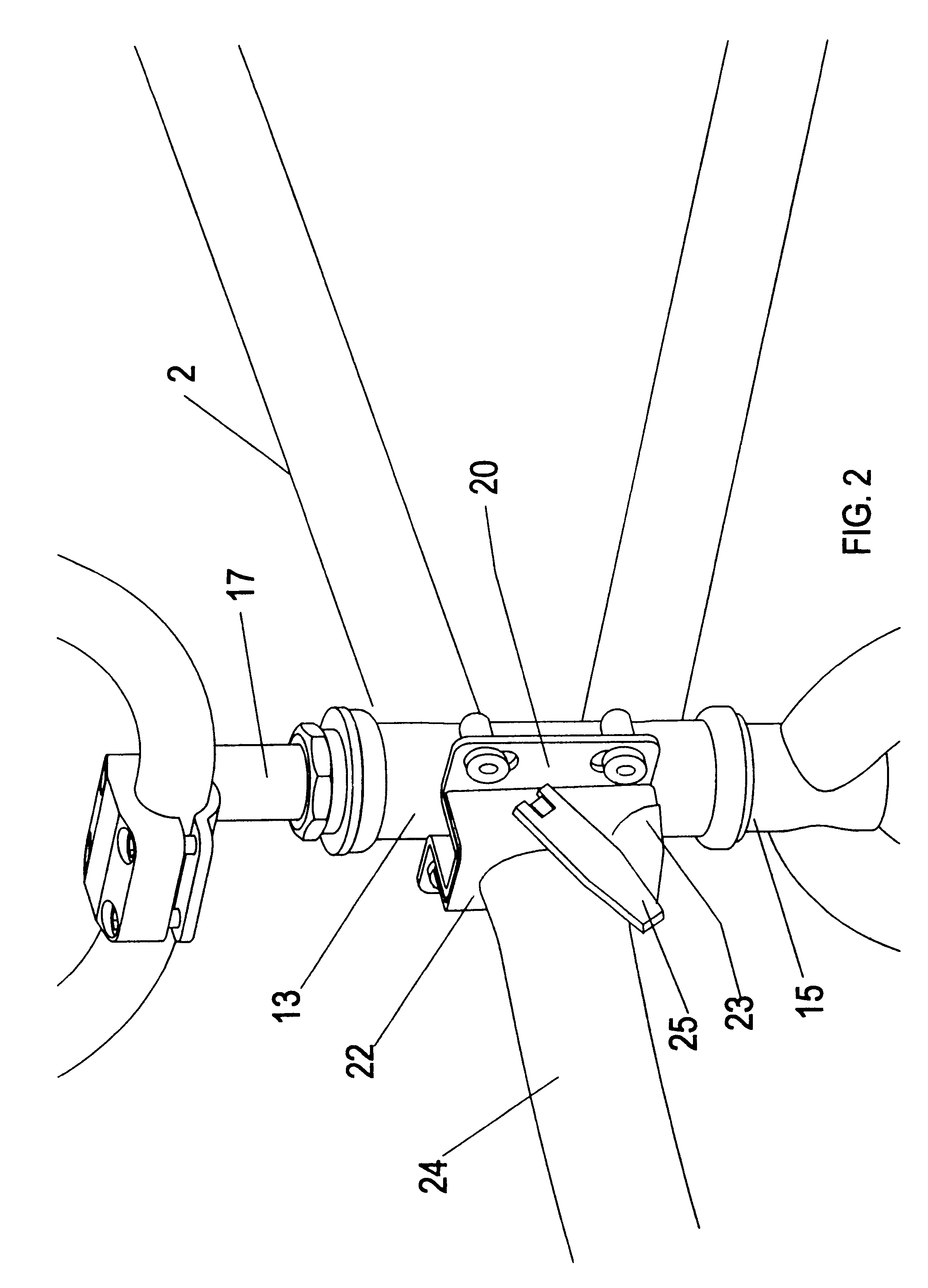
The present invention comprises a receiver component, such as receiver member 20 or a pivot receiver 30, attached to the head tube 13 of a child's bicycle 2 and a coupler member 22 that depends from the distal end of a bicycle tow bar 24 connected to a larger adult bicycle 4, so that when coupler member 22 is fully joined to receiver member 20 or pivot receiver 30, the adult bicycle 4 can safely tow the child's bicycle 2. In its attached tandem position, the front wheel 6 of the child's bicycle 2 is preferably elevated and unable to engage the ground so that the rider (not shown) of the adult bicycle 4 maintains steering control. Although not shown, the child can optionally pedal or coast while being towed. Connection between receiver member 20, or pivot receiver 30, and coupler member 22 is rapidly made. Coupler member 22 is first attached to the distal end of tow bar 24, while receiver member 20 or pivot receiver 30 is connected to the head tube 13 of the child's bicycle 2. The op...


PUM


Abstract

A steering lock, and a method of use, for connecting child's bicycle (2) behind adult bicycle (4), with the front wheel (6) of child's bicycle (2) being elevated so that the adult rider retains steering control. The steering lock comprises receiver (20) or pivot receiver (30) attached to the head tube (13) of child's bicycle (2), a coupler (22) attached to a bicycle tow bar (24) on adult bicycle (4), and a steering lock pin (10). As coupler (22) is secured against receiver member (20) or pivot receiver (30) with quick-release safety pin (25), steering lock pin (10) is forced through aligned holes in head tube (13), steering fork tube (15), and handlebar stem tube (17) on child's bicycle (2) to lock one to the other during tandem travel. Thus, child's bicycle (2) can be expediently converted from independent operation to a tandem configuration multiple times during the same ride.

Description

This invention relates to devices for attaching two bicycles to one another during use, specifically to a steering lock, and a method for its use, which can be used with a bicycle tow bar to rapidly and securely attach a child's bicycle behind the larger bicycle of an adult for tandem travel. In its towed position the front wheel of the child's bicycle is preferably elevated and unable to engage the ground, thus allowing the adult rider to retain steering control while the child chooses to pedal or coast. One end of the bicycle tow bar is connected to the adult bicycle, with the coupler member of the steering lock being attached to the opposing distal end of the tow bar. The steering lock of the present invention also comprises a receiver member that is attachable to the head tube of the child's bicycle. Thus, when the coupler member becomes engaged with the receiver member, while the front wheel of the child's bicycle is also in the longitudinally directed position required to alig...

Claims


Application Information

Patent Timeline
Patent Type & Authority Patents(United States)
IPC IPC(8): B62K27/12B62H5/00B62H5/02B62K27/00B62K13/00B62K13/02
CPCB62H5/02B62K13/02B62K27/12
Inventor NELSON, EDWARD SCOTT
Owner NELSON EDWARD SCOTT
Learn More