
Combination light-weight deck form, with connectors

a lightweight, connector technology, applied in the direction of rod connections, bridges, couplings, etc., can solve the problems of significant and achieve the effect of improving the reliability and durability of the concrete deck of the bridg

Inactive Publication Date: 2003-09-23
KWON HEUG JIN
View PDF16 Cites 30 Cited by
  • Summary
  • Abstract
  • Description
  • Claims
  • Application Information

AI Technical Summary

Benefits of technology

Accordingly, a primary object of the present invention is to provide a light-weight and durable, and yet reliable structure for a concrete bridge deck form.
It is a further and more particular object of the present invention to provide a structure for a concrete bridge deck form which is capable of prefabrication and installation, in a quick and reliable manner.
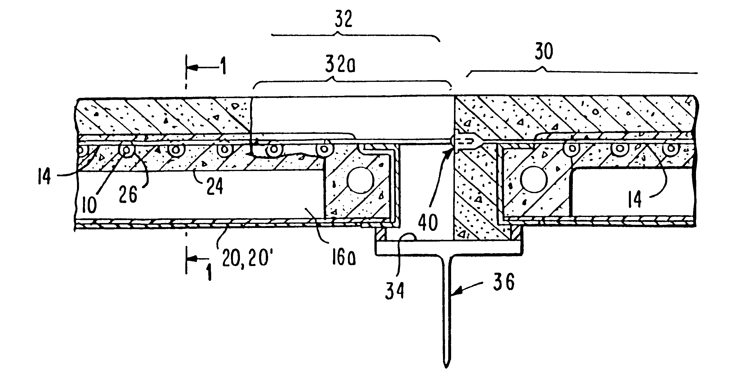
These and other objects of the present invention are provided in a bridge deck form which features preferred and alternative embodiments of light-weight concrete deck forms for bridges and reinforcement bar connectors for easy installation, which enables prefabrication thereof and quick and reliable installation, as well as durability. The form itself includes reinforcement bars, longitudinal beam stiffeners and thin plates, welded to the beam stiffeners. In the preferred embodiment, the thin plates are attached to the bottom flanges of the longitudinal beam stiffeners, whether they be in the form of T-beams or I-beams. For that preferred embodiment, the thin plate is corrugated with hills and valleys, and with the valleys occurring approximately midway between longitudinal beam stiffeners, and the "hills" attached to the bottom flange of the longitudinal beam stiffeners. In an alternative embodiment, the thin plate is planar, attached to the bottom flanges and generally planar therewith. In either event, for the preferred embodiment or the alternative embodiment mentioned above, the space below the concrete slab, between the thin plate and the top portion or top flange (inverted T-beam and I-beam, respectively) of each longitudinal beam stiffener has filler material (styrofoam or similar material). A further alternative embodiment does not have filler material of styrofoam or similar material, as with the preferred and first alternative embodiments, but instead the thin plate attaches in a generally planar configuration to web plates near the upper portion of the longitudinal beam stiffeners. For purposes of quick and reliable fabrication at the site of the bridge, a preferred and alternative mechanical connector for the above prefabricated deck forms includes a male connector element and a female connector element, wherein each includes V-shaped grooves occupying less than one-quarter of the circumference for the male member and the female member at two opposed positions of the circular shape. Accordingly, with the balance of the circular male element and female opening hole having smooth surfaces, the connection between the members for connecting reinforcement bars, requires only insertion and a quarter turn to mechanically connect reinforcement bars of concrete slab elements. Therefore, original fabrication of bridge decks, with prefabricated concrete slabs is quick and reliable; and replacement of broken concrete slabs is also quick and reliable.

Problems solved by technology

In recent years, vehicles that are heavier and faster-moving, with their constant pounding on bridges, have presented problems of reliability and durability for the concrete decks of bridges to a significant extent.

Method used


Image

  • Combination light-weight deck form, with connectors
  • Combination light-weight deck form, with connectors
  • Combination light-weight deck form, with connectors

Examples


Embodiment Construction

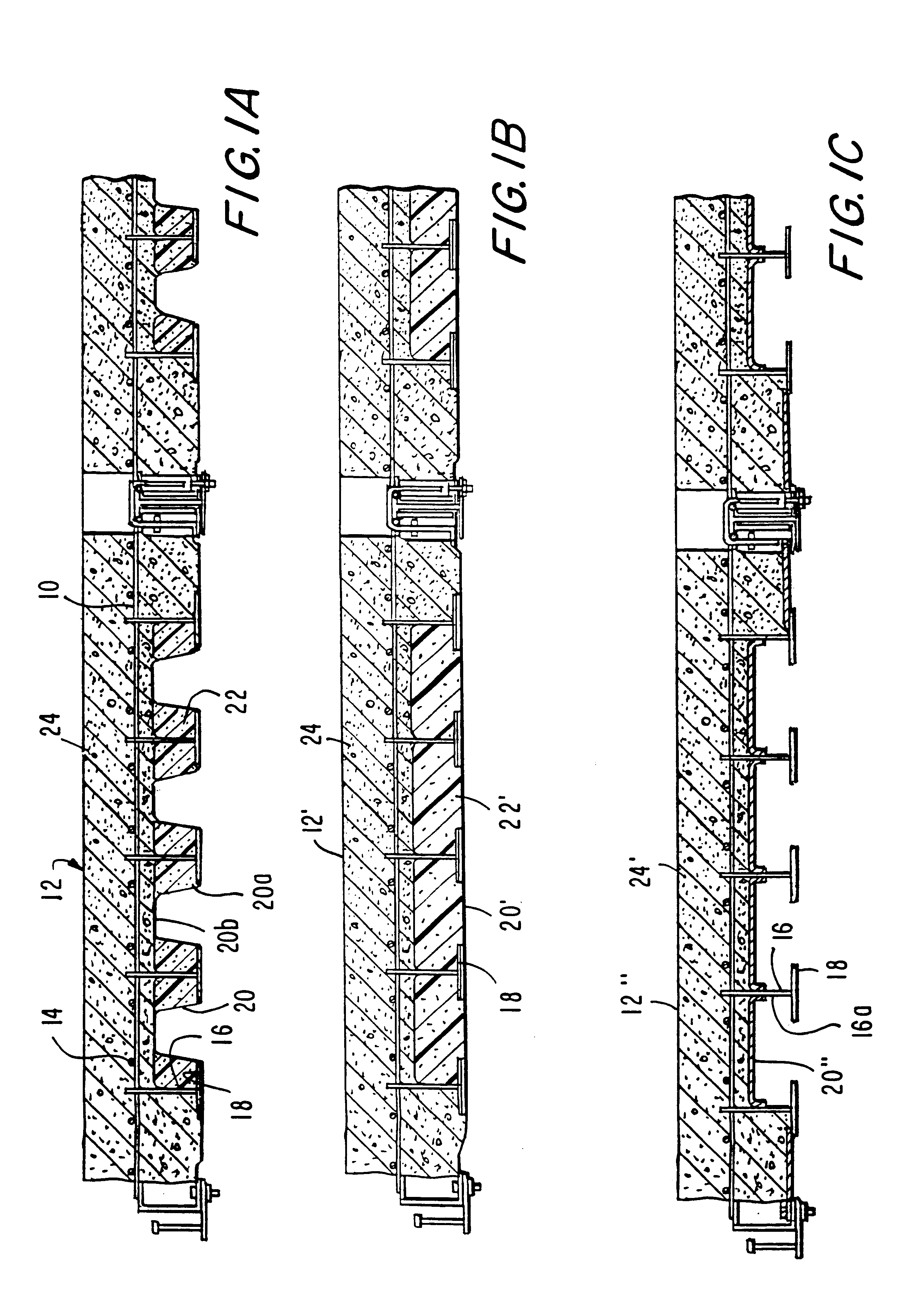
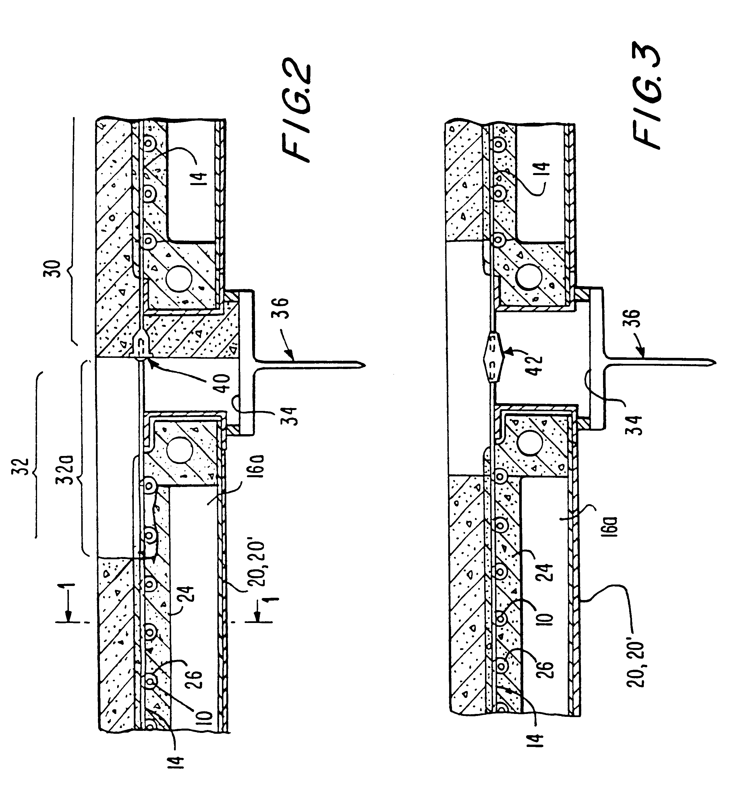
Referring to the drawings, and particularly FIGS. 1A-1C, cross-sectional views are shown to illustrate transverse reinforcement bars 10 of prefabricated, light-weight deck forms generally designated 12. The longitudinal reinforcement bars 14 are arranged perpendicular to the transverse reinforcement bars 10. Longitudinal beam stiffeners 16 are shown in FIGS. 1A-1C in the form of an inverted T-shape, with the bottom flange 18 of the longitudinal beam stiffeners having welded to them a light-guage, thin plate 20.

In FIG. 1A, the thin plate 20 is in corrugated form with hills 20a and valleys 20b, so that thin plate 20 encompasses filler material 22, using a non-metallic material such as styrofoam or the like.

In an alternative embodiment, thin plate 20' is shown in FIG. 1B as extending in the transverse direction of form 12' without hills and valleys to enclose filler material 22'. As with FIG. 1A, the embodiment of FIG. 1B shows the use of filler material 22 and 22' as filling the tensi...


PUM


Abstract

The disclosure sets forth pre-fabricated deck forms and reinforcement bar connectors for light-weight concrete decks on bridges. The three different types of deck forms disclosed provide light-weight and composite concrete decks for bridges, with reinforcement bars, longitudinal beam stiffeners and thin plates, and the longitudinal beam stiffeners, welded to the thin plates. The thin plates are attached to the bottom flanges of the longitudinal beam stiffeners for the first two types, and to the web plates of those stiffeners, for the third type. The bottom portion of the first two types of deck forms disclosed are filled with filler material, such as styrofoam or similar non-metallic material. In one type, the filler material is provided under the concrete slab only proximate the longitudinal beam stiffeners, and the thin plate is corrugated. In the second type, the thin plate is planar, and the filler material completely fills the lower half of the area between the longitudinal beam stiffener and the bottom flanges thereof, to which the planar thin plate is attached. The third type of form uses a thin plate, as well, but without filler material, the thin plate adhering to the longitudinal beam stiffeners at a position similar to the position of the valleys of the corrugations in the first type of form.

Description

This invention relates primarily to reinforcement bar connectors for construction joints between concrete deck forms for bridges, and for providing light-weight concrete deck forms for bridges, with the mechanical bar connectors being useful also for any reinforced concrete structure, to connect the reinforcement bars.In recent years, vehicles that are heavier and faster-moving, with their constant pounding on bridges, have presented problems of reliability and durability for the concrete decks of bridges to a significant extent. Of course, bridge superstructures have been made more redundant and it has been attempted to reduce the dead weight of the bridge. In making these changes, it has become increasingly important to quickly accomplish any bridge repairs in order to avoid prolonged traffic congestion. Therefore, it would be helpful to provide simple, reliable and durable deck forms and connectors in a manner which confronts not only the goals of a quicker installation time, but...

Claims


Application Information

Patent Timeline
Patent Type & Authority Patents(United States)
IPC IPC(8): E01D19/12
CPCE01D19/125E01D2101/268Y10T403/7005Y10T403/7009E04C5/165
Inventor KWON, HEUG JIN
Owner KWON HEUG JIN
Learn More