Circuit for the dynamic control of ceramic solid-state actuators

a ceramic solid-state actuator and actuator technology, applied in piezoelectric/electrostrictive devices, piezoelectric/electrostrictive devices, magnetostrictive device details, etc., can solve the problem of high output power of the driver circuit, linear transfer behaviour cannot be guaranteed for frequencies up to any magnitude, and expansion has an inherent error of up to 10%, both with respect to its absolute valu

Inactive Publication Date: 2003-09-09
GSG ELEKTRONIK +1
View PDF21 Cites 20 Cited by
  • Summary
  • Abstract
  • Description
  • Claims
  • Application Information

AI Technical Summary

Benefits of technology

The basic idea of the invention is to form the control circuit for the dynamic operation of piezotranslators as a half-bridge circuit with a single series coil as an intermediate energy store. In this case, the maximum available current for charging and discharging the piezotranslator is identical with the maximum current of the series coil. Such a limitation occurs unchanged and at a constant limit current over the entire range of the piezo output voltage. For the capacitance of the piezotranslator the constant limit current causes a constant voltage increase so that the storage capacity of the intermediate energy store is uniformly and fully utilised over the entire working range. The installation size can be reduced due to the use of a single series coil, with the indirect consequence of a cost reduction.
The described advantage of the improved pilot control also has a positive influence of those control loops in which an additional positioning control by means of a further controller is dispensed with. These advantages are particularly effective at the upper limit of the working frequency range where the loop amplification must be reduced because of the operational stability and is therefore too low for an effective error compensation.

Problems solved by technology

Due to the high capacitance of the piezotranslators, however, a high output power of the driver circuit is required in the case of fast positional changes as they occur under dynamic operation conditions.
However, such a linear transfer behaviour cannot be ensured for frequencies up to any magnitude, but is limited, on the one hand, by the resonance frequency of the translator or the entire actuating system, respectively, and by the output power of the amplifier, on the other hand.
The resulting expansion has an inherent error of up to 10%, both with respect to its absolute value and to its relative movements.
Due to the fact that piezotranslators can electrically be described as capacitors, as mentioned above, onto which electric charges must either be applied or from which said charges must be withdrawn for the purpose of a length variation, which for example can be realised by means of a switch, charging or discharging between the piezotranslator, on the one hand, and the charging current circuit, on the other hand, will inevitably result in power losses, if this is done via controllable variable resistors,. e.g. transistors.
In the middle output range, however, the available storage volume cannot be utilised so that a correspondingly implemented output amplifier does not operate efficiently.
However, problems occur with a corresponding use in energy recovering control circuits.
The series resonance circuit in turn causes a high increase of the amplification in the resonance range, together with an undesired phase shift in the working band of the control loop approaching the critical 180.degree. limit, which affects the compensation.
From this, an undesired post-pulse oscillation or self-oscillation results.
The desired flat amplitude characteristic of the overall system up to the upper working frequency range is therefore no longer achievable.
Also otherwise present drawbacks due to voltage losses at the energy recovery diodes do no longer occur in a comparable magnitude.
These advantages are particularly effective at the upper limit of the working frequency range where the loop amplification must be reduced because of the operational stability and is therefore too low for an effective error compensation.

Method used


Image

  • Circuit for the dynamic control of ceramic solid-state actuators
  • Circuit for the dynamic control of ceramic solid-state actuators
  • Circuit for the dynamic control of ceramic solid-state actuators

Examples


Embodiment Construction

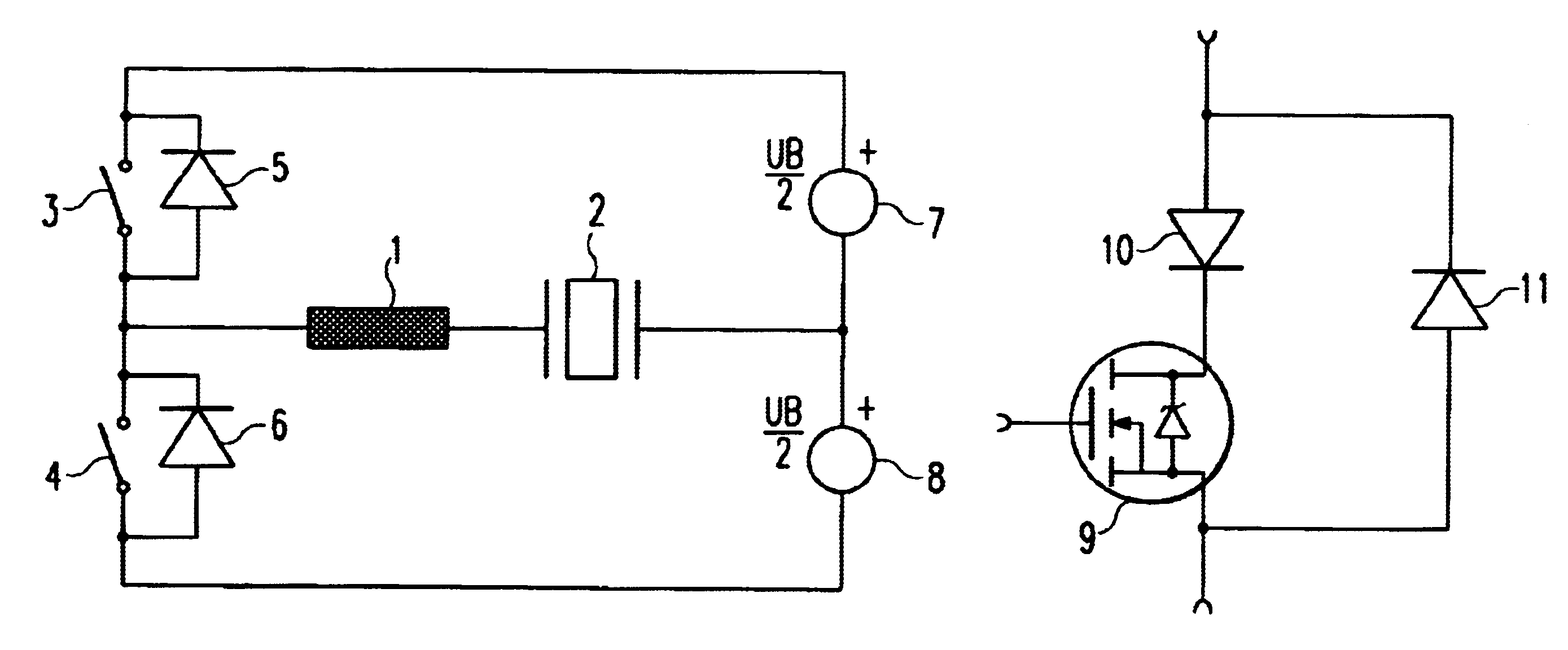
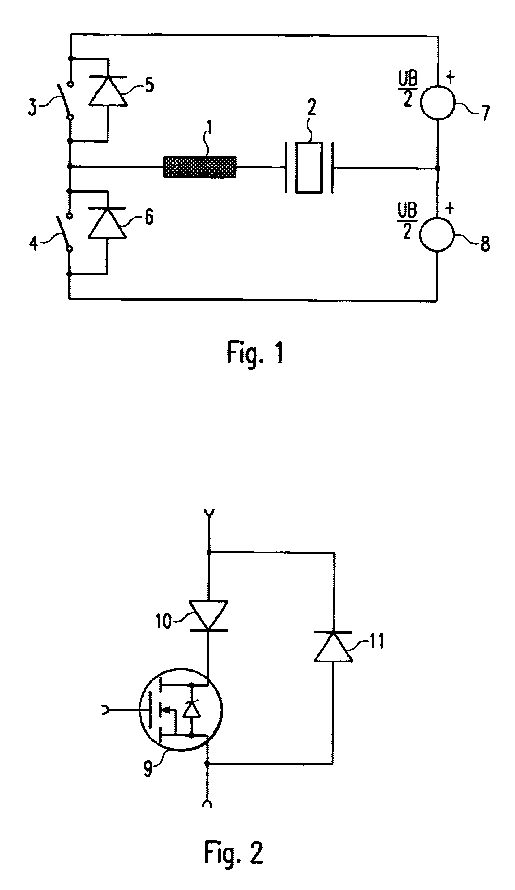
As can be seen, a single inductive intermediate store 1 is connected in series with the piezotranslator 2. The illustrated secondary circuit shows a half-bridge arrangement, with switches 3 and 4 being externally clocked with up to 100 kHz. The switches 3 and 4 are bridged by energy recovery diodes 5 and 6. In the configuration of the switches 3 and 4 as MOSFETs such diodes are integral members of this transistor family.

Voltage sources 7 and 8 for one half-bridge each are formed by a switched-mode power supply known per se and comprise suitably dimensioned storage capacities.

The coil direct current is superimposed by a low, high-frequency direct current of small amplitude in the working cycle of the half-bridges. The only energy store 1 reduces the storage volume with respect to size and is operative both during charging as well as discharging of the piezotranslator's capacitance, i.e. over the entire operating time.

Compared to the known state of the art, the switching losses accord...


PUM


Abstract

The invention relates to a circuit arrangement for the dynamic control of ceramic solid-state actuators, such as piezotranslators with energy recovery by means of magnetic intermediate stores and / or storage capacitors as well as by clocked switches. For achieving a predetermined linear voltage characteristic at the piezotranslator, according to the invention, a single inductive intermediate store is arranged in the secondary circuit, which is connected in series with the piezotranslator, and the secondary circuit is designed as a half-bridge. The switches provided in the respective half-bridge are controlled at a high cycle or switching frequency by an external controller, with the series connection of piezotranslator and inductive intermediate store furthermore carrying a superimposed bridge direct current in order to ensure the desired charging of the capacitance of the piezotranslator, on the one hand, and to optimize the energy recovery, on the other hand.

Description

1. Field of the InventionThe invention relates to a circuit arrangement for the dynamic control of -ceramic solid-state actuators, such as for example, piezotranslators with energy recovery by means of magnetic intermediate stores as well as a control loop for operating a piezotranslator.2. Description of the Related ArtPiezotranslators are electrically controllable actuators whose functions can be attributed to the piezoelectric effect. Active sensors, so-called actuators, can perform the most delicate positioning movements with high accuracy from the subnanometer up to the millimeter range.Under electrical aspects, a piezotranslator represents a capacitor whose charge has a proportional relationship to its expansion. Consequently, piezotranslators take up energy during the expansion process only. The expansion is maintained without further energy supply. Due to the high capacitance of the piezotranslators, however, a high output power of the driver circuit is required in the case ...

Claims


Application Information

Patent Timeline
IPC IPC(8): H01L41/00H01L41/04H02N2/06
CPCH02N2/062H02N2/065
Inventor KNAUSS, UWE
Owner GSG ELEKTRONIK
Why Eureka
Try Eureka