Air bag gas inflator

Inactive Publication Date: 2003-06-03
DAICEL CHEM IND LTD
View PDF18 Cites 11 Cited by
  • Summary
  • Abstract
  • Description
  • Claims
  • Application Information

AI Technical Summary

Benefits of technology

Also, when the degree of an impact is large, those two ignition units operate simultaneously, thereby increasing the inflating rate of the air bag. As a result, the air bag is inflated rapidly, thereby forming a cushion in front of the driver.
As stated in the foregoing, the present invention realizes a gas generator for an air bag, in which the deployment speed of the bag can be varied. Namely, in the gas generator of the present invention (the pressurized chamber), containing pressurized gas therein, is divided into two sections by a partition, and the two sections are connected by the through-hole. Further, by providing two ignition units, the initial inflating (deploying) speed of the air bag is reduced to move the driver / passenger to a proper seating posture when the driver / passenger is not seated in the proper seating posture, and then applying a greater force to the passenger / driver and provide a cushion in front of the passenger. When the shock due to the collision is relatively large, the air bag is inflated at a greater speed, to inflate the air bag more quickly, to provide the cushion in front of the passenger to protect the passenger.
The gas generator of the present invention has a simpler structure, less number of parts, and therefore, easier and less expensive to manufacture.

Problems solved by technology

Therefore, an excessive force, due to the deployment of the bag, may be applied to the passengers.
By this method, however, although the deployment force of the bag can be selected in accordance with the extent of the shock applied to the vehicle, the deployment of the bag cannot be selected in accordance with the seating posture of the passengers.
The structure of this gas generator device, however, is very complicated and includes many parts.
Therefore, it is very difficult to manufacture and to maintain reliability.
Also, when the degree of an impact is large, those two ignition units operate simultaneously, thereby increasing the inflating rate of the air bag.

Method used


Image

  • Air bag gas inflator
  • Air bag gas inflator
  • Air bag gas inflator

Examples


Embodiment Construction

An experiment was conducted using the gas generator shown in FIG. 1 under the following conditions.

CONDITIONS

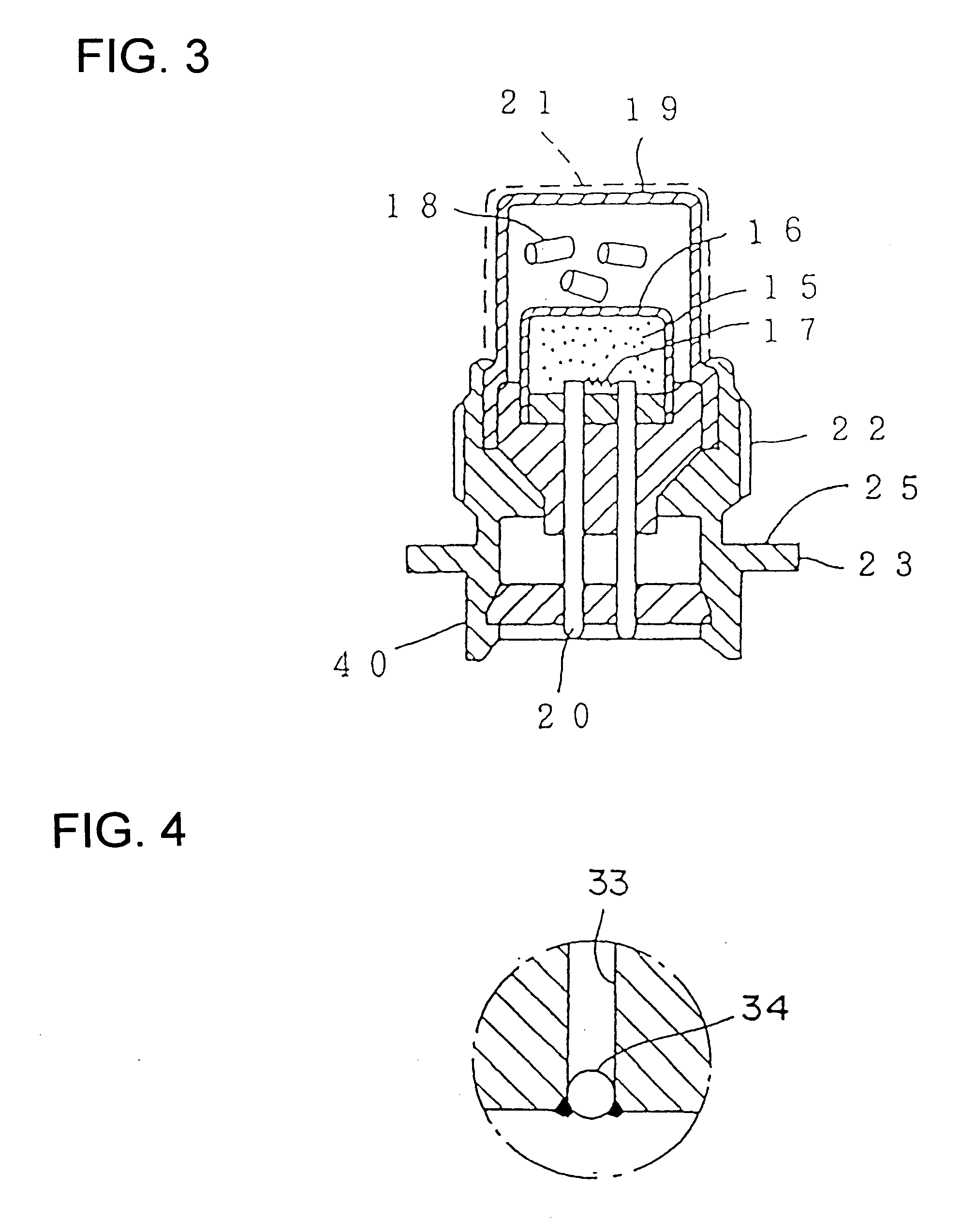
The volume of the first accommodation chamber section: 30 ml.

The volume of the second accommodation chamber section: 50 ml.

Pressurized gas: A mixture of gases consisting of argon 75%, oxygen 20%, and helium 5% is filled under a pressure Of 4000 psi (280 kg / cm.sup.3).

Gas tight-sealing wall: A stainless steel having 0.2 mm thickness is TIG-welded.

The first ignition unit: a mixture 100 mg of KClO.sub.4 and Zr as the igniter material and nitramine powder product 3.2 gr as the gas generating agents.

The second ignition unit: a mixture 100 mg of KClO.sub.4 and Zr as the igniter material and nitramine powder product 1.2 gr as the gas generating agents.

The through-holes: 4 holes each having 3.0 mm diameter.

FIG. 5 shows a gas generator in accordance with another embodiment of the present invention. The gas generator includes a vessel 1', a partition 2', through-holes 3', two ignition u...


PUM


Abstract

A gas generator for an air bag that can change the inflating (deploying) speed of the air bag is provided. The gas generator includes a vessel having a pressurized gas accommodation chamber for accommodating pressurized gas therein, a partition that divides the pressurized gas accommodation chamber into two sections, and a through-hole which is defined in the partition, for communicating the two sections. The gas generator also includes two ignition units containing gas generating agents therein, and a gas release unit disposed in the pressurized gas accommodation chamber and having a rupturable gas sealing wall. A single ignition unit can be disposed in each section or two ignition units can be disposed in one of the two sections.

Description

1. Technical FieldThe present invention relates to a gas generator for an air bag that protects a driver or a passenger from an impact, and more particularly to a hybrid-type gas generator that seals pressurized gas therein.2. Description of the Prior ArtFor the purpose of protecting a driver or passenger from an impact, a vehicle is equipped with an air bag device. The air bag device includes a sensor, a control unit, gas generator, an air bag, etc. The gas generator includes ignition means and gas generating means.Upon detection of an impact by the sensor, a detection signal is supplied to a control unit, which conducts arithmetic calculation in response to the detection signal. The control unit sends an output signal representative of the result of the arithmetic calculation to the ignition means. The ignition means is thus operated. By this operation, a gas is generated abruptly and provided into the air bag (bag body). As a result, the air bag is inflated and forms a cushion th...

Claims


Application Information

Patent Timeline
IPC IPC(8): B60R21/26B60R21/263B60R21/272
CPCB60R21/272B60R2021/2685B60R2021/2633
Inventor IYOSHI, SHUSOFUKABORI, MITHUHIKO
Owner DAICEL CHEM IND LTD
Why Eureka
Try Eureka