Level-tracing water-monitoring apparatus
a water monitoring and level-tracing technology, applied in the direction of liquid/fluent solid measurement, instruments, machines/engines, etc., can solve the problems of increasing water treatment costs, harming human bodies, aquatic life, and affecting the quality of life of the water supply
- Summary
- Abstract
- Description
- Claims
- Application Information
AI Technical Summary
Benefits of technology
Problems solved by technology
Method used
Image
Examples
first embodiment
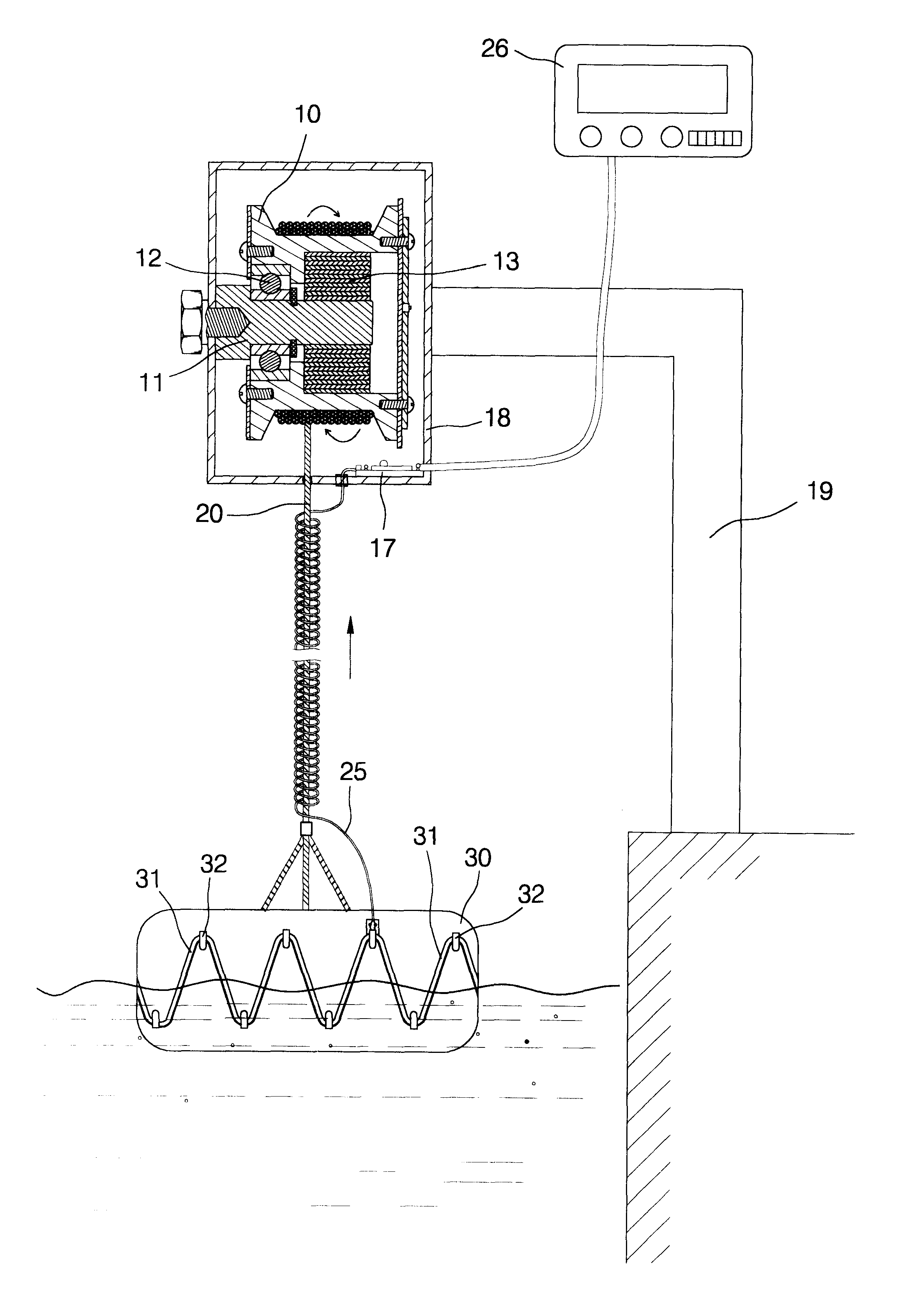
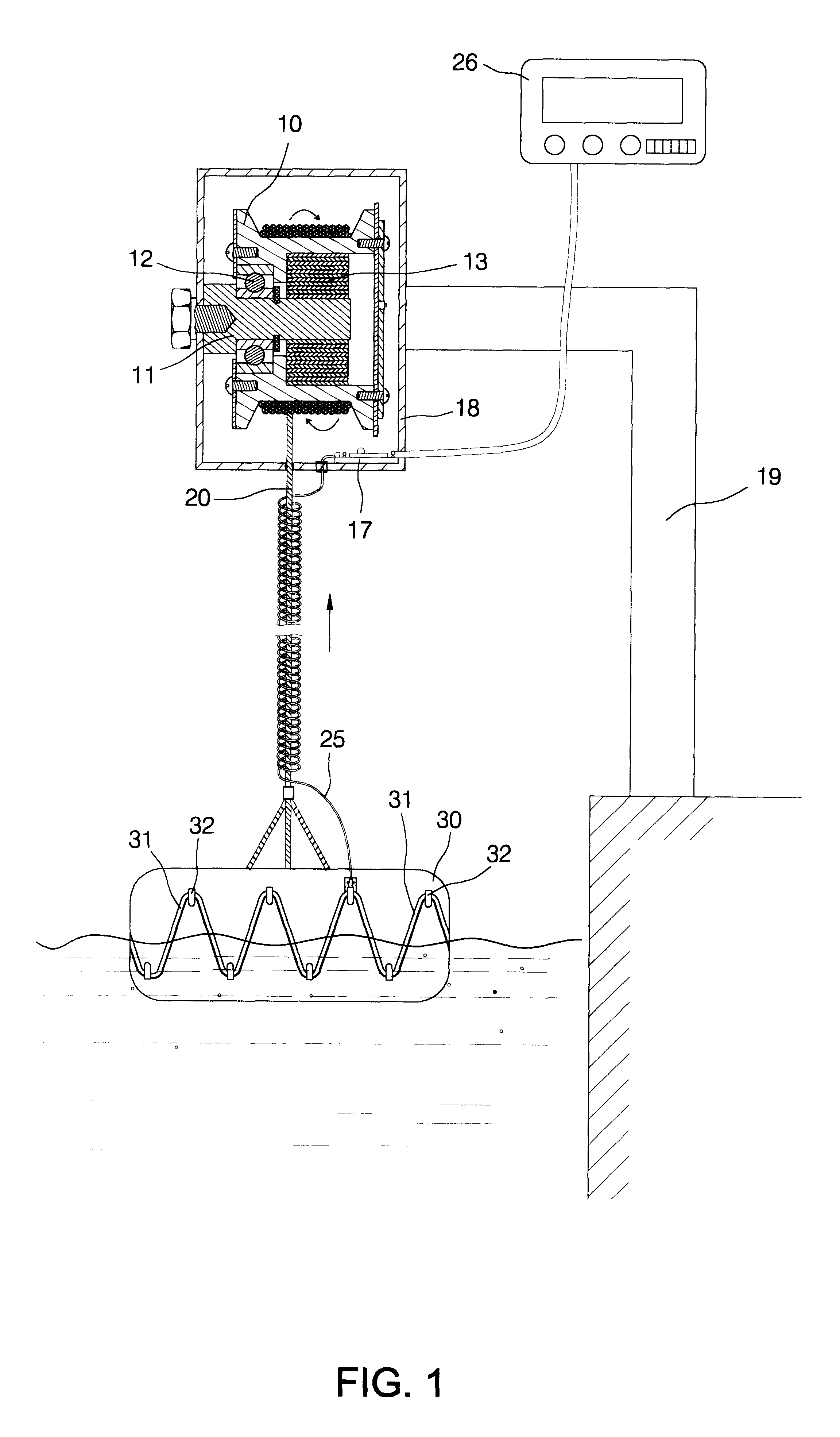
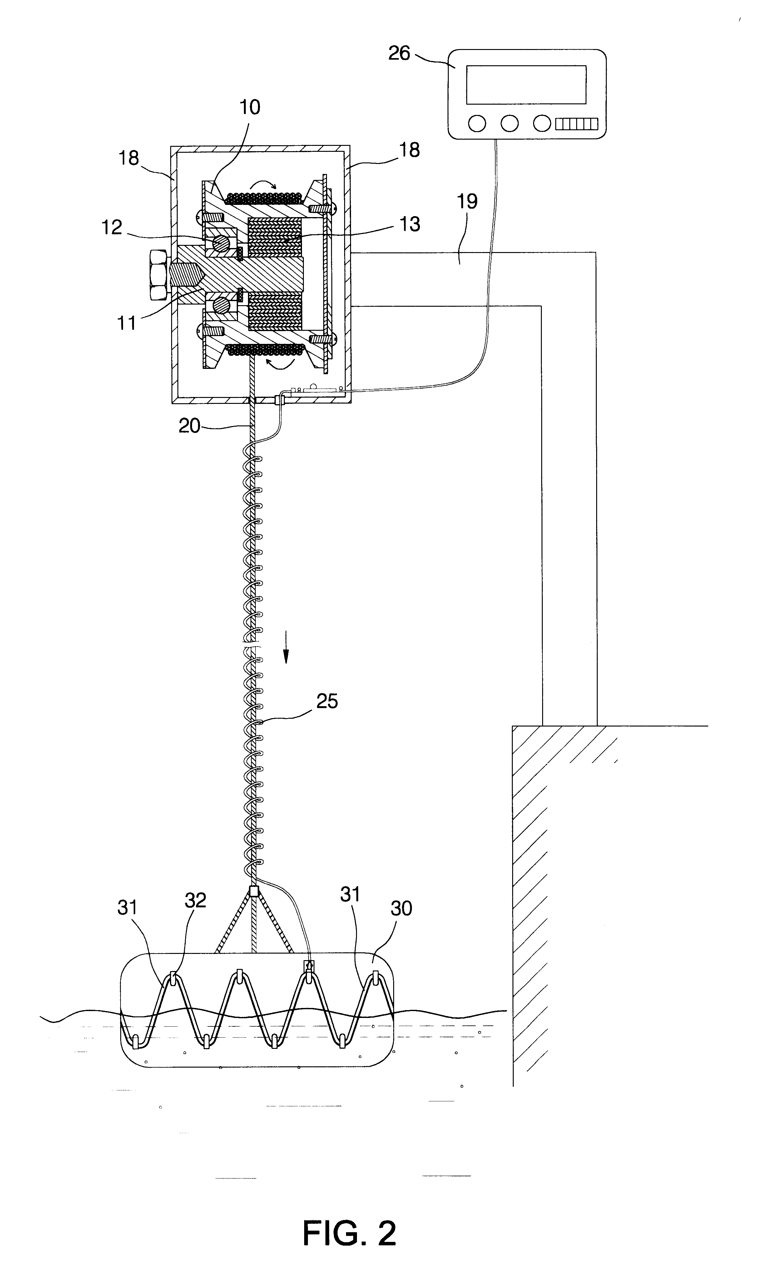
FIG. 1 shows a water-monitoring apparatus according to an embodiment of the present invention. The water-monitoring apparatus is installed in an appropriate position by the water.
The water-monitoring apparatus includes a box 18 for supporting a number of components thereof (to be described). A frame 19 includes a first end secured to the bank and a second end extending to a position above the water surface. The box 18 is attached to the second end of the frame 19.
A shaft 11 is mounted on a wall of the box 18. A reel 10 is mounted on a middle section of the shaft 11 by means of a bearing 12 so that the reel 10 is allowed to rotate with respect to the shaft 11. The reel 10 includes a cylindrical body and two flanges each formed at an end of the cylindrical body.
A coil spring 13 is connected between the shaft 11 and the reel 10. The coil spring 13 includes a first end connected with a second end of the shaft 11 and a second end connected with the reel 10. The coil spring 13 is selected...
second embodiment
FIG. 3 shows a water-monitoring apparatus according to a second embodiment of the present invention. The hydrocarbon sensor 31 of the first embodiment is replaced with a number of sensors 35 in the second embodiment. Each sensor 35 is used to produce a signal representative of an environmental parameter and, more particularly, a water quality parameter such as pH, temperature, oxygen content, conductivity, chlorine content, turbidity, heavy metal content, etc. The signal wire 25 is electrically connected through the circuit board 33 with the sensors 35. The circuit board 33 may be designed to periodically acquire the primary signals from the sensors 35, e.g., once every minute, and to stay in a power-saving mode for the rest of every minute.
third embodiment
FIG. 4 shows a third embodiment of the present invention. The coil spring 13 of the first and second embodiments is replaced with a constant force motor spring 16 because the latter provides a force varying within a smaller range. An axle 14 is mounted on a wall of the box 18 by means of a bearing 15. A first drum 21 is secured to the axle 14. A second drum 22 is mounted on the wall of the box 18 in a rotational manner. The constant force motor spring 16 includes a first section connected with and wound on the first drum 21 and a second section connected with and wound on the second drum 22. The axle 14 is connected with the reel 10 so that they are allowed to rotate together. Thus, the constant force motor spring 16 exerts a constant force on the reel 10 through the axle 14.
PUM
 Abstract
Description
Claims
Application Information
 - R&D
- Intellectual Property
- Life Sciences
- Materials
- Tech Scout
- Unparalleled Data Quality
- Higher Quality Content
- 60% Fewer Hallucinations
Browse by: Latest US Patents, China's latest patents, Technical Efficacy Thesaurus, Application Domain, Technology Topic, Popular Technical Reports.
© 2025 PatSnap. All rights reserved.Legal|Privacy policy|Modern Slavery Act Transparency Statement|Sitemap|About US| Contact US: help@patsnap.com


