
Valve for controlling fluids

a valve and fluid technology, applied in the direction of fuel injecting pumps, generators/motors, machines/engines, etc., can solve the problem of only achieving a higher transmission ratio, e.g., approximately 1:8

Inactive Publication Date: 2003-03-11
ROBERT BOSCH GMBH
View PDF10 Cites 11 Cited by
  • Summary
  • Abstract
  • Description
  • Claims
  • Application Information

AI Technical Summary

Benefits of technology

The valve according to the invention, has the advantage over the prior art that the combination of hydraulic and mechanical pressure intensifiers solves the oscillation problem in a simple form since the hydraulic pressure intensifier no longer has to be divided. At the same time, the hydraulic pressure intensifier performs the temperature compensation between the piezoelectric actuator and the housing so that the temperature change disadvantages which are common with purely mechanical pressure intensifiers can be compensated for. Consequently, the valve for controlling fluids according to the invention can be used to achieve a uniform reproducibility of injections so that precisely defined injection times and / or injection quantities of fuel can be assured. Furthermore, a mechanical pressure intensifier is simply designed and can be inexpensively produced so that advantages that pertain to it can also be achieved with regard to a second hydraulic pressure intensifier. Moreover, the mechanical pressure intensifier does not have any problems due to contamination of hydraulic fluid so that the maintenance costs with regard to a second hydraulic pressure intensifier are considerably reduced.In a particularly advantageous embodiment, the mechanical pressure intensifier can have a lever which transmits the stroke of the piston element to the valve member. Levers can be simply designed and inexpensively produced and result in a rugged embodiment of the valve.The lever is advantageously supported on a support which divides the lever into two lever arms. In a simple form, this presents the possibility of adapting the transmission ratio to the corresponding preset conditions. At the same time, the cooperation of the lever and support can achieve a precise transmission of the stroke of the piezoelectric actuator onto the valve member. In this connection, a lever arm length ratio of 4:1 has turned out to be particularly advantageous.The piston element is preferably embodied as a push rod. In the field in question, push rods are standard components which can be simply and inexpensively produced.In the valve for controlling fluids according to the invention, the transmission surface area of the push rod and the associated surface area of the piezoelectric actuator produce a transmission ratio of 2:1. This low transmission ratio of the hydraulic pressure intensifier assures a low oscillation susceptibility of the hydraulic pressure intensifier. On the other hand, this transmission ratio is added to the predetermined lever arm length ratio of 4:1, resulting in a total transmission ratio of 8:1 so that the desired transmission ratio is achieved without oscillation problems.In addition, in the valve for controlling fluids according to the invention, a piston associated with the piezoelectric actuator can be disposed between the pressure chamber and the piezoelectric actuator. On the one hand, this piston transmits the longitudinal expansion from the piezoelectric actuator to the push rod and on the other hand, prevents the piezoelectric actuator from coming into contact with the hydraulic fluid. In order to further improve this seal between the piezoelectric actuator and hydraulic fluid, the transition region between the piezoelectric actuator and the associated piston in sealed with a sealing element.

Problems solved by technology

In valves of this kind, there is the problem that a higher transmission ratio, e.g. approximately 1:8, can only be achieved with correspondingly high error tolerances since external influences such as temperature increase in the engine compartment or also losses in the pressure medium, as error components, have a very strong influence on the transmission ratio.
On the other hand, these divided hydraulic pressure intensifiers have turned out to be susceptible to oscillation to which in turn leads to imprecision.

Method used


Image

  • Valve for controlling fluids
  • Valve for controlling fluids
  • Valve for controlling fluids

Examples


Embodiment Construction

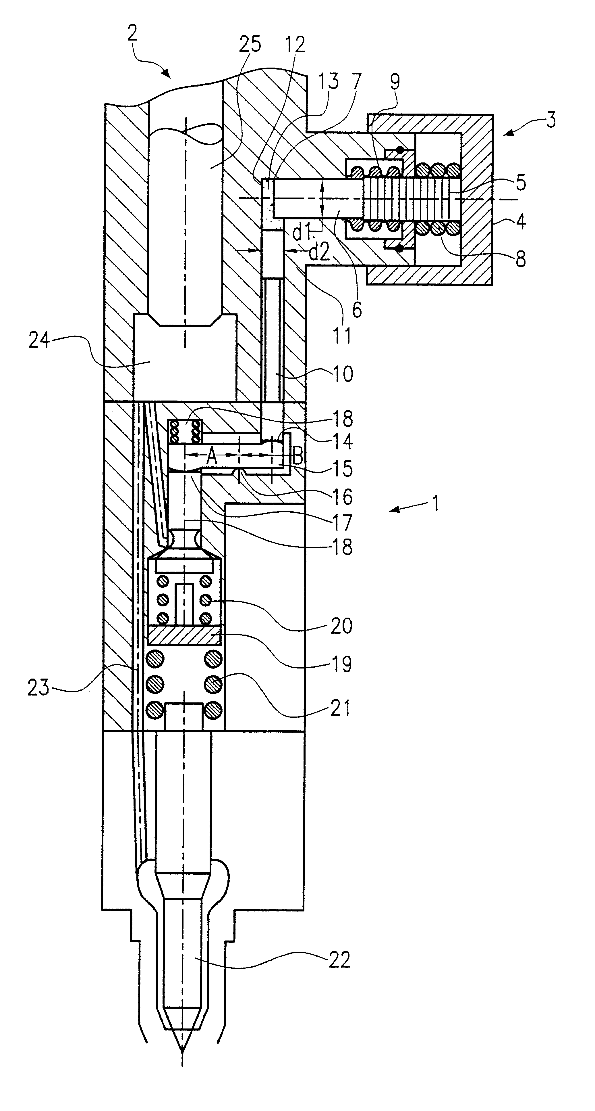
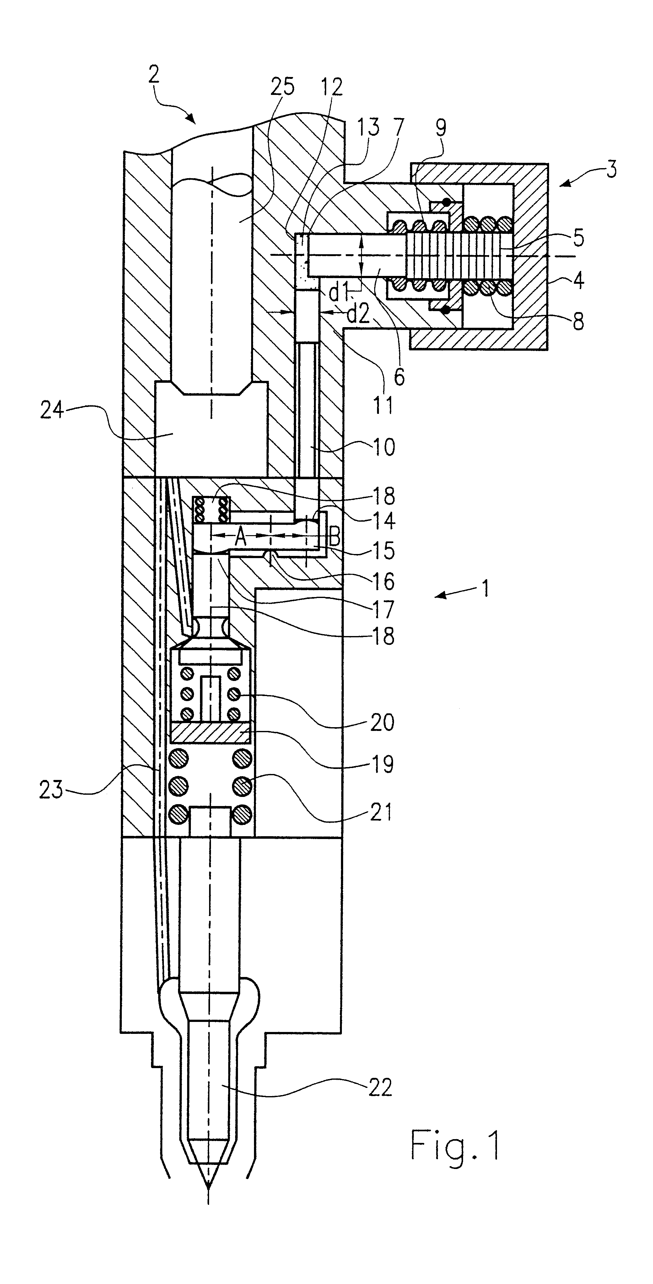
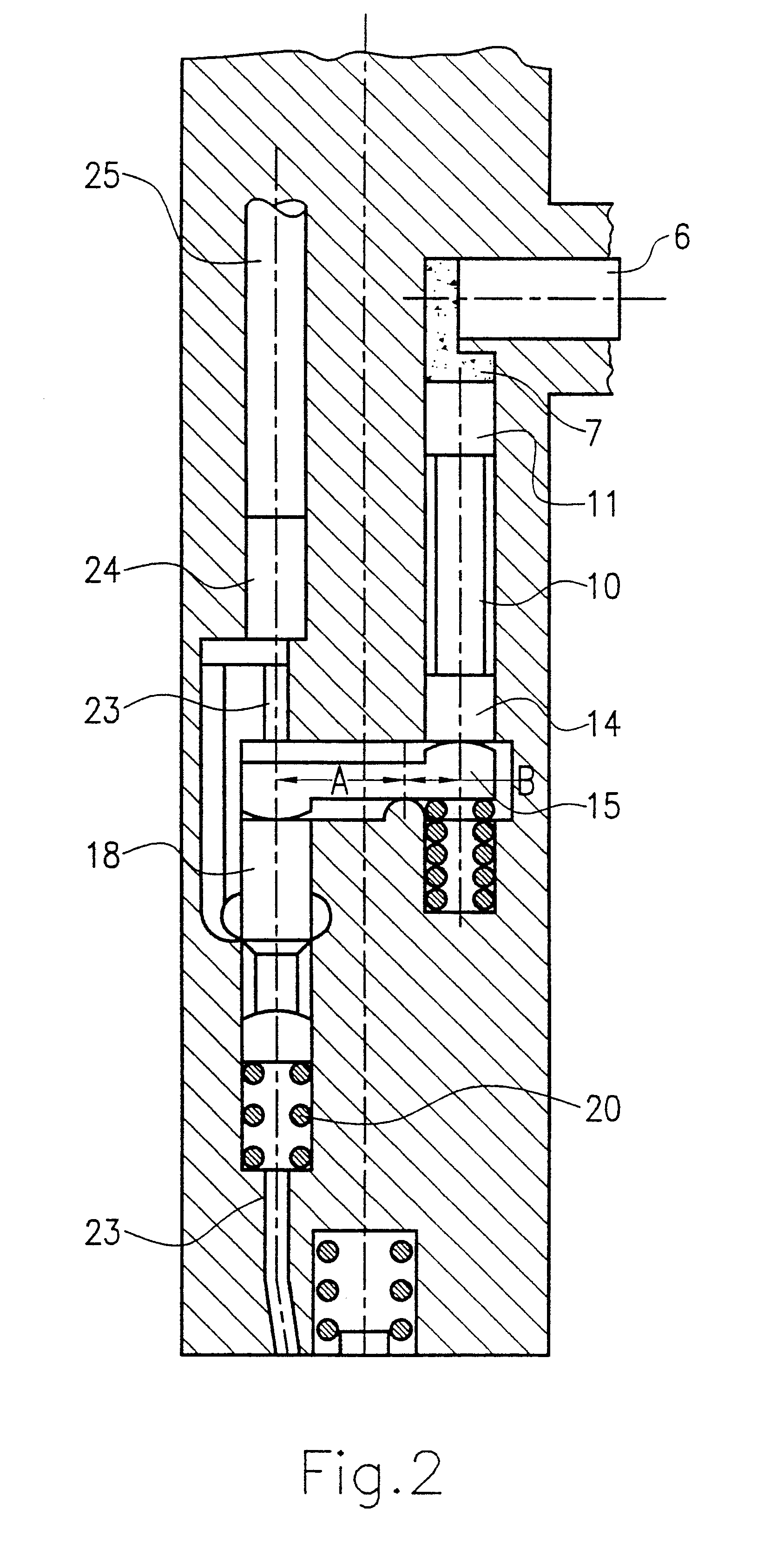
In the first exemplary embodiment shown in FIG. 1, the valve according to the invention is used in an injection system in which the injection pump and the injector constitute a unit (a so-called unit injector system (UIS)). An injection system of this kind is shown in FIG. 1. The injection valve 1 is comprised of a pump unit 2 and a control unit 3. The control unit 3 includes a piezoelectric actuator 5 disposed in a housing 4. The piezoelectric actuator 5 communicates with a hydraulic pressure chamber 7 via a piston 6. In this connection, the piezoelectric actuator 5 is prestressed toward the housing 4 by a prestressing spring 8; a sealing element 9 is disposed at the transition region between the piston 6 and the piezoelectric actuator 5 in such a way that the piezoelectric actuator is not exposed to the fluid in the hydraulic pressure chamber 7.

In FIG. 1, a push rod 10 with an end region 11 adjoins the pressure chamber 7 at a 90.degree. angle to the piston 6. In this connection, t...


PUM


Abstract

A valve for controlling fluids is proposed, which has a piezoelectric actuator (5) and a hydraulic pressure intensifier which transmits the stroke of the piezoelectric actuator (5). The hydraulic pressure intensifier has a pressure chamber (7) and a piston element (10) with a transmission surface area (12). The hydraulic pressure intensifier can actuate a valve member (18) that is connected to the piston element (10). A mechanical pressure intensifier is interposed between the hydraulic pressure intensifier and the valve member (18).

Description

PRIOR ARTThe invention relates to a valve for controlling fluids.EP-0 477 400 A1 describes a valve of this kind in which an actuating piston of the valve member is movably disposed in a stepped bore of the valve housing, in a small diameter part of the stepped bore. A larger piston that can be moved by means of a piezoelectric actuator is disposed in a larger diameter part of the stepped bore. A hydraulic chamber filled with a pressure medium is disposed between the two pistons so that a movement of the piezoelectric actuator is hydraulically transmitted. This means that when the larger piston is moved a certain distance by the piezoelectric actuator, the actuating piston of the valve member executes a stroke that is enlarged by the transmission ratio of the piston diameter because the piston of the piezoelectric actuator has a larger surface area than the actuating piston of the valve member. In this connection, the valve member, the actuating piston of the valve member, the piston...

Claims


Application Information

Patent Timeline
Patent Type & Authority Patents(United States)
IPC IPC(8): F02M57/00F02M59/46F02M59/20F02M57/02F02M59/36F02M59/00F02M51/00H02N2/04
CPCF02M57/02F02M59/366F02M59/468F02M2200/703F02M2200/701
Inventor BOECKING, FRIEDRICH
Owner ROBERT BOSCH GMBH
Learn More