
Automated banking machine enclosure

Inactive Publication Date: 2003-03-04
DIEBOLD NIXDORF
View PDF11 Cites 122 Cited by
  • Summary
  • Abstract
  • Description
  • Claims
  • Application Information

AI Technical Summary

Benefits of technology

It is a further object of the present invention to provide an automated banking machine enclosure that is sufficiently durable to withstand placement in an unattended outdoor environment.
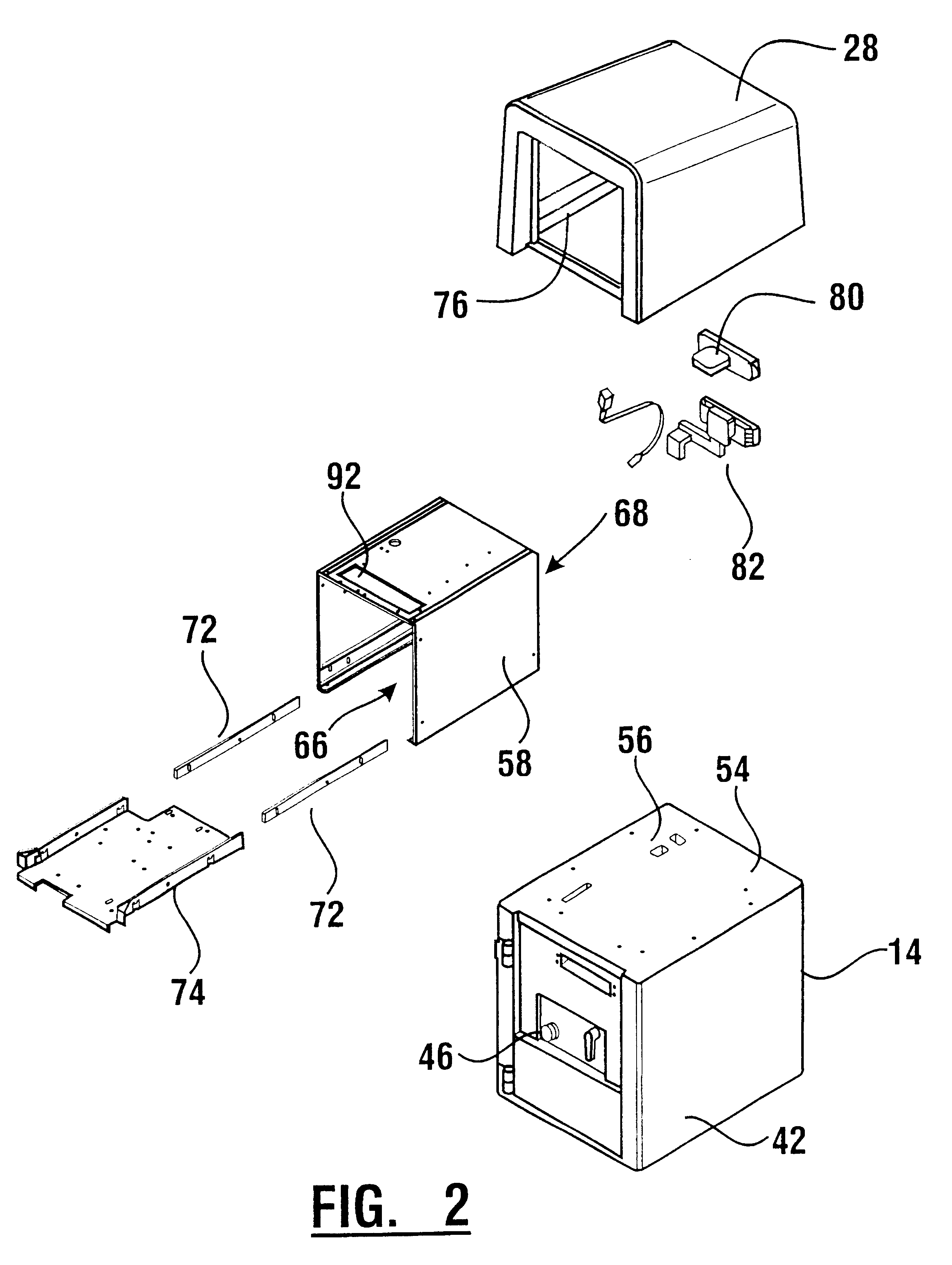
The automated banking machine further includes a generally one piece nonmetallic body. In an exemplary embodiment the body is made of a polymer. The polymer body is in operatively supporting engagement with the frame and extends in generally surrounding relation of the input devices and the display screen. The body includes at least one opening through which the display screen may be viewed and / or at least one input device may be accessed. In certain preferred forms of the invention. the polymer body is comprised of a reaction injection molded (RIM) thermoset olefin material, which enables producing machines with an attractive appearance, provides weather resistance, and provides resistance to many forms of attack.

Problems solved by technology

This adds to the cost of the machine.
There are sometimes locations external to building lobbies where it would be desirable to position an ATM, but there is insufficient room to construct a vestibule or similar enclosure.
For these locations there is no satisfactory banking machine which can be installed.
While a machine designed for installation in a lobby may be placed in the location, such machines are generally not resistant to the elements and damage would soon occur due to exposure.
Such damage may commonly occur due to infiltration of moisture and dirt into the machine and extremes of heat and cold.
In addition, exterior locations are often unattended.
This results in a greater risk of damage and break-in to the machine.
Lobby units generally are not built to withstand lengthy attacks by machine tools that could more readily be attempted in an unattended external environment.

Method used


Image

  • Automated banking machine enclosure
  • Automated banking machine enclosure
  • Automated banking machine enclosure

Examples


Embodiment Construction

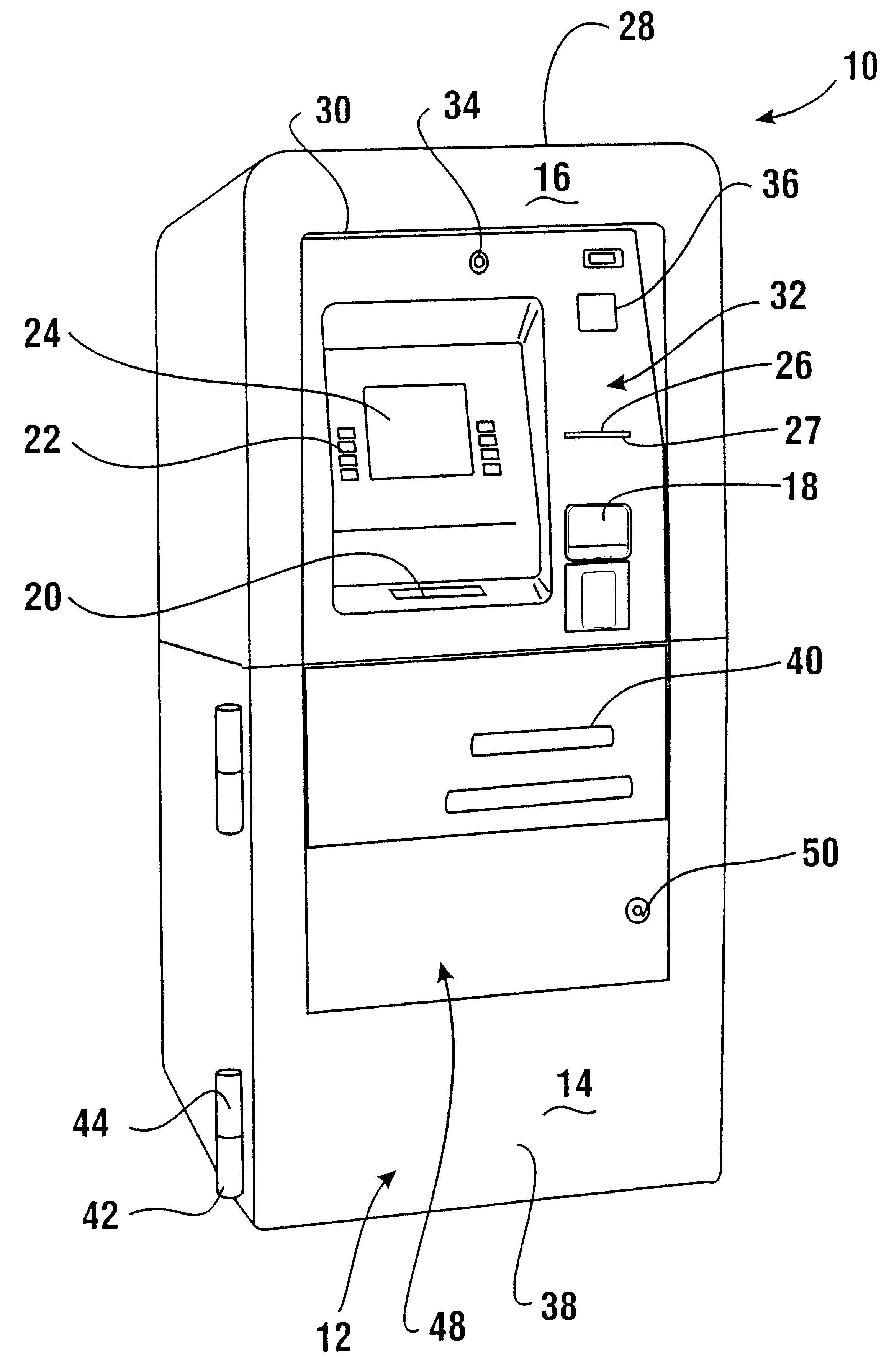
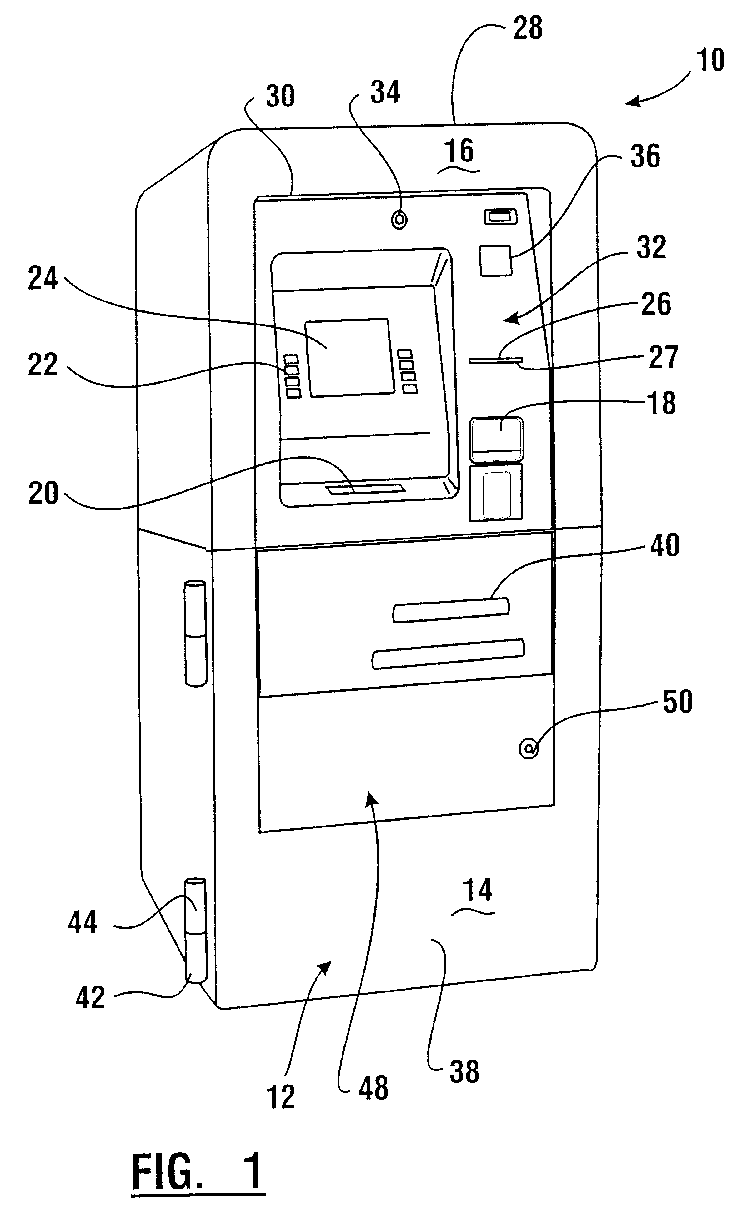
Referring now to the drawings and particularly to FIG. 1, there is shown therein an automated banking machine of a first exemplary embodiment of the present invention generally indicated 10. Automated banking machine 10 of this exemplary embodiment is an ATM suitable for conducting banking transactions. Machine 10 includes an enclosure generally indicated 12. Enclosure 12 includes a lower chest portion 14 and an upper portion 16.

Machine 10 includes input devices including a card reader schematically indicated 18. The card reader may comprise a magnetic type card reader, smart card reader or other device for reading card shaped articles. A fascia 32 includes a slot in generally aligned relation with the card reader. Other input devices on the exemplary machine include a keypad 20 and function buttons 22. Machine 10 further includes at least one output device such as a display screen 24. The display screen may have a touch screen. A printer 26 is positioned within the machine and also...


PUM


Abstract

An automated banking machine includes a chest portion (14). Transaction function devices such as an input device (18) and a display screen (24) are supported on the chest portion. A generally one-piece polymer body (28) is operatively engaged relative to the chest portion and extends in generally surrounding relation of the input device and display screen. The body includes at least one opening (30) such that the display screen is visible and the input device is accessible through the body.

Description

This invention relates to automated banking machines. Specifically this invention relates to an enclosure structure for an automated banking machine.Automated banking machines are known in the prior art. A common type of automated banking machine is an automated teller machine (ATM). Users operate ATMs to conduct banking transactions. Transactions commonly conducted at ATMs include dispensing cash, making deposits, making account balance inquiries, making transfers between accounts, paying bills, cashing checks and other types of automated transactions. Other types of automated banking machines perform different or additional functions such as dispensing tickets, dispensing or receiving gaming materials, or providing payment for goods or services. For purposes of this disclosure any machine that is capable of accomplishing transactions involving transfers of value shall be considered an automated banking machine.Automated banking machines include enclosures that house components use...

Claims


Application Information

Patent Timeline
IPC IPC(8): G07F19/00A47B81/00G07F9/00G07G5/00
CPCG07F19/205G07F19/20
Inventor LEWIS, KIM R.LUTE, JR., RICHARD C.
Owner DIEBOLD NIXDORF
Learn More