Optical alignment in capillary detection using capillary wall scatter
a technology of optical alignment and capillary wall, applied in the direction of optical radiation measurement, fluorescence/phosphorescence, luminescent dosimeter, etc., can solve the problem of insignificant relative range of motion required by the pivotal mount, the difference between the refractive index of the channel contents, and the signal is relatively noisy
- Summary
- Abstract
- Description
- Claims
- Application Information
AI Technical Summary
Benefits of technology
Problems solved by technology
Method used
Image
Examples
example 2
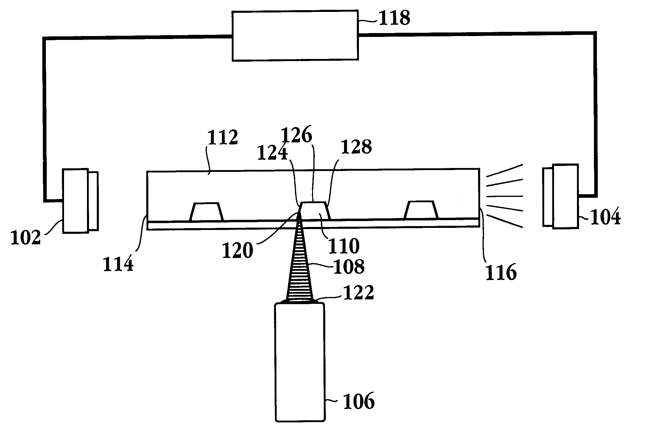
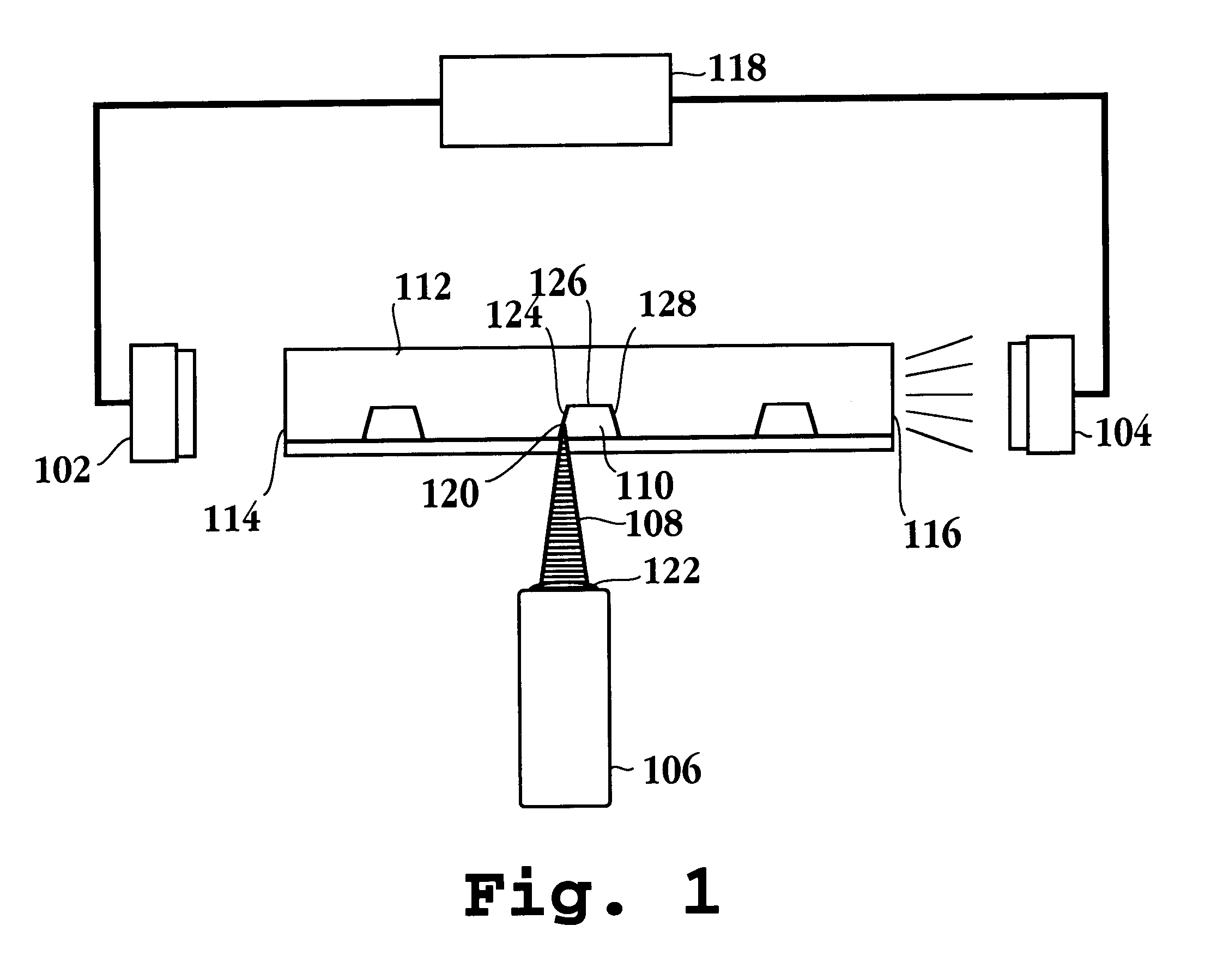
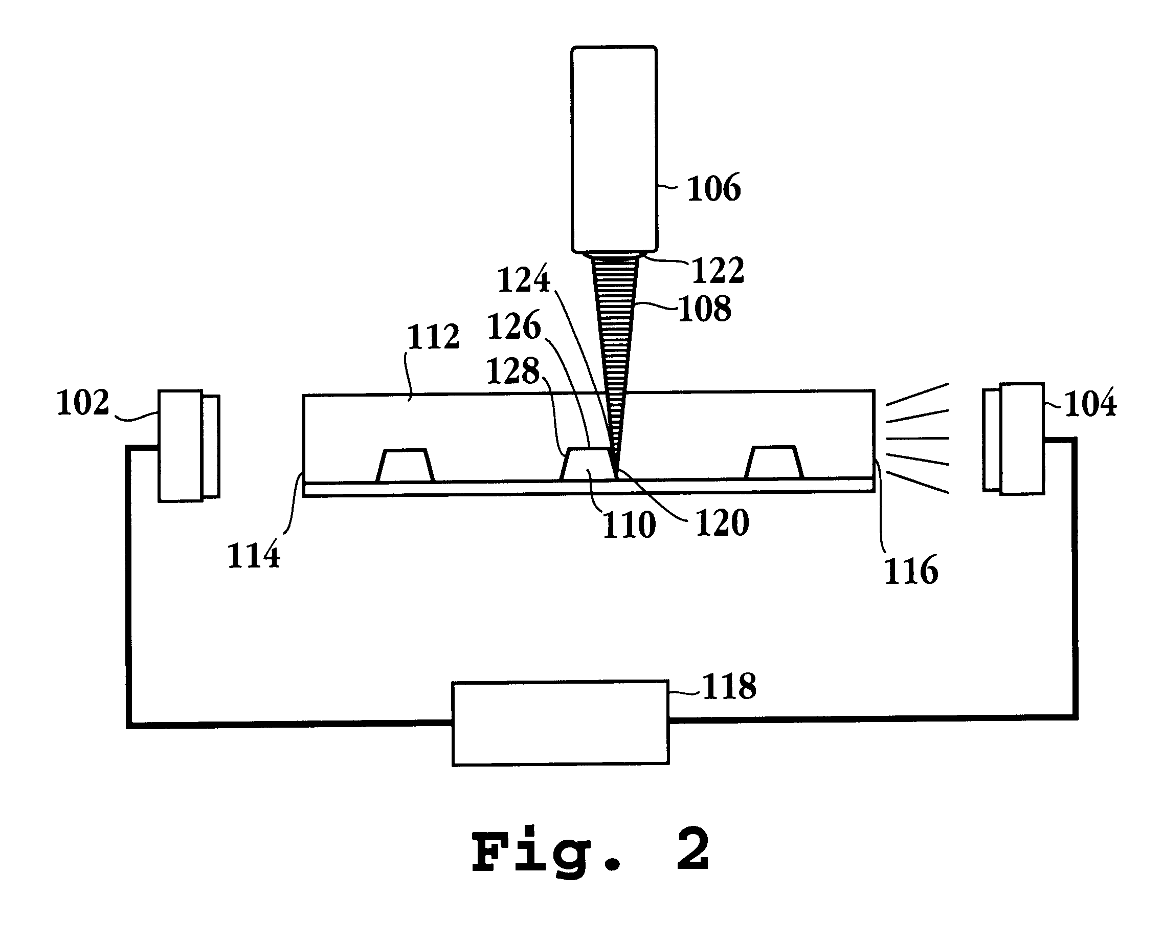
In the following example, the same equipment as above is used where two scatter detectors located on opposite sides of the lab chip are used to characterize a symmetrical channel profile and align the optical detection system relative to the channel's geometric center. Unlike the example above, a fluorescent standard loaded into the channel is not required.
A model lab chip is removably mounted to the carriage system after which its position relative to the laser source is placed in registry. The laser is then aligned at a detection zone adjacent to one of the microfluidic analysis channels. With reference to FIG. 7, samples of probable data are presented. As above, a laser scan of the channel profile is conducted provided however that scatter signals are generated at opposite edges of the lab chip presenting two Gaussian shaped peaks 702 and 704, one corresponding to each side wall of the channel. Due to the symmetry of the channel cross section, the center of the channel for purpos...
PUM
| Property | Measurement | Unit |
|---|---|---|
| width | aaaaa | aaaaa |
| length | aaaaa | aaaaa |
| width | aaaaa | aaaaa |
Abstract
Description
Claims
Application Information
 - R&D
- Intellectual Property
- Life Sciences
- Materials
- Tech Scout
- Unparalleled Data Quality
- Higher Quality Content
- 60% Fewer Hallucinations
Browse by: Latest US Patents, China's latest patents, Technical Efficacy Thesaurus, Application Domain, Technology Topic, Popular Technical Reports.
© 2025 PatSnap. All rights reserved.Legal|Privacy policy|Modern Slavery Act Transparency Statement|Sitemap|About US| Contact US: help@patsnap.com


