
Engine exhaust control

a technology for exhaust control and engine, which is applied in the direction of electrical control, machines/engines, output power, etc., can solve the problems of pressure leakage, difficulty in conjunction with these valves, and inability to achieve so great clearan

Inactive Publication Date: 2003-01-21
YAMAHA MOTOR CO LTD
View PDF24 Cites 8 Cited by
  • Summary
  • Abstract
  • Description
  • Claims
  • Application Information

AI Technical Summary

Benefits of technology

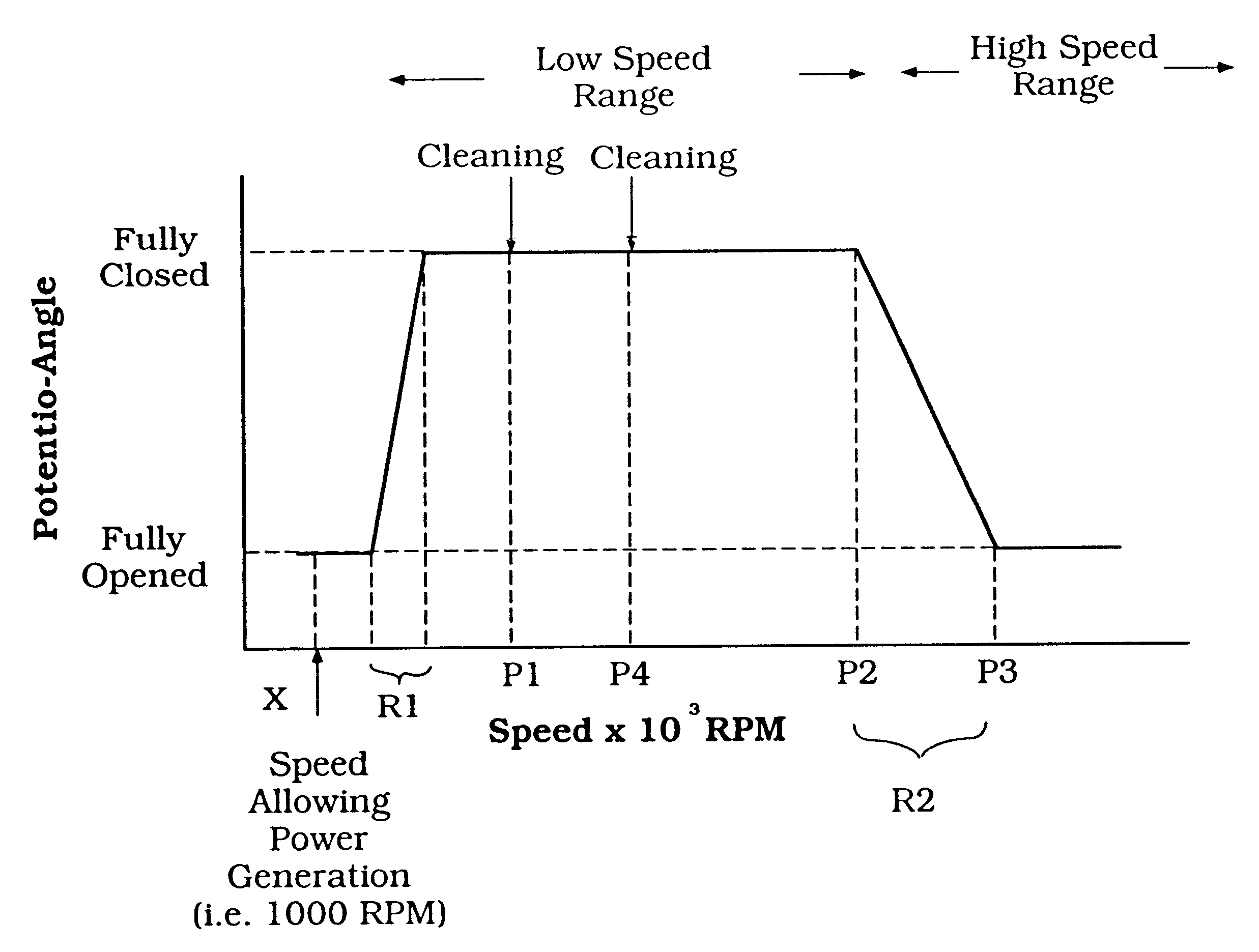
Another feature of the present invention provides an improved exhaust control valve system and method of operating the same. Additionally, an exhaust control valve system configured in accordance with the present invention desirably provides a method for cleaning an exhaust control valve under at least some conditions that may reduce the possibility of valve sticking on start up and during low-temperature operation. Moreover, the exhaust control valve system preferably prioritizes the acceleration of the engine over the cleaning operation.

Problems solved by technology

Generally, these valves are of the sliding or rotating type, and do not serve to ever completely close the opening or port in each combustion chamber in two-stroke applications.
There is a difficulty in conjunction with these valves however.
Of course, this clearance cannot be so great as to cause pressure leakage.
Therefore, when the engine is started, before the engine is warmed-up, the valves are more prone to sticking.
Moreover, because these valves have a relatively small range of movement, and are not continuously moved, they may seize within the guide passage in which they are mounted.
In addition, because oil may be present in the exhaust gases of two cycle engines, the oil can cause a further problem once the engine is shut off.
However, as a stopped engine cools, residual oil may carbonize, or coke, on the control valve and form deposits.
These deposits, along with other foreign matter, such as sea-salt for instance, make it difficult to operate the valve when the engine is restarted.
In short, these deposits tend to inhibit a smooth operation of the valve.
However, the cycling of the exhaust control valve presents problems in and of itself.
This can result in uneven acceleration as well as an uncomfortable ride.

Method used


Image

  • Engine exhaust control
  • Engine exhaust control
  • Engine exhaust control

Examples


Embodiment Construction

The present invention generally relates to an engine powering a planing-type boat, such as a personal watercraft. Specifically, the invention relates to a control strategy for an exhaust control valve associated with the engine powering the boat.

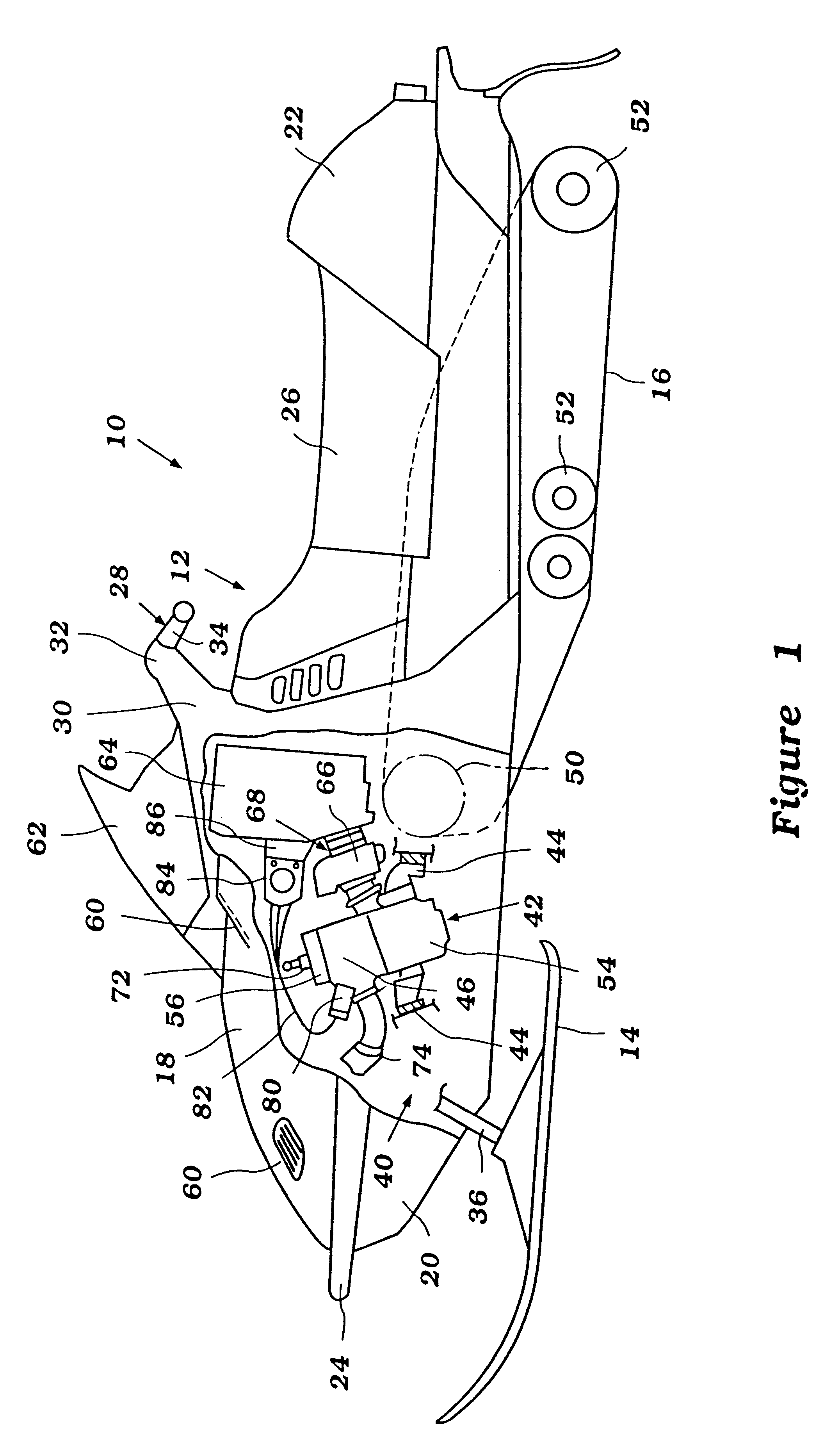
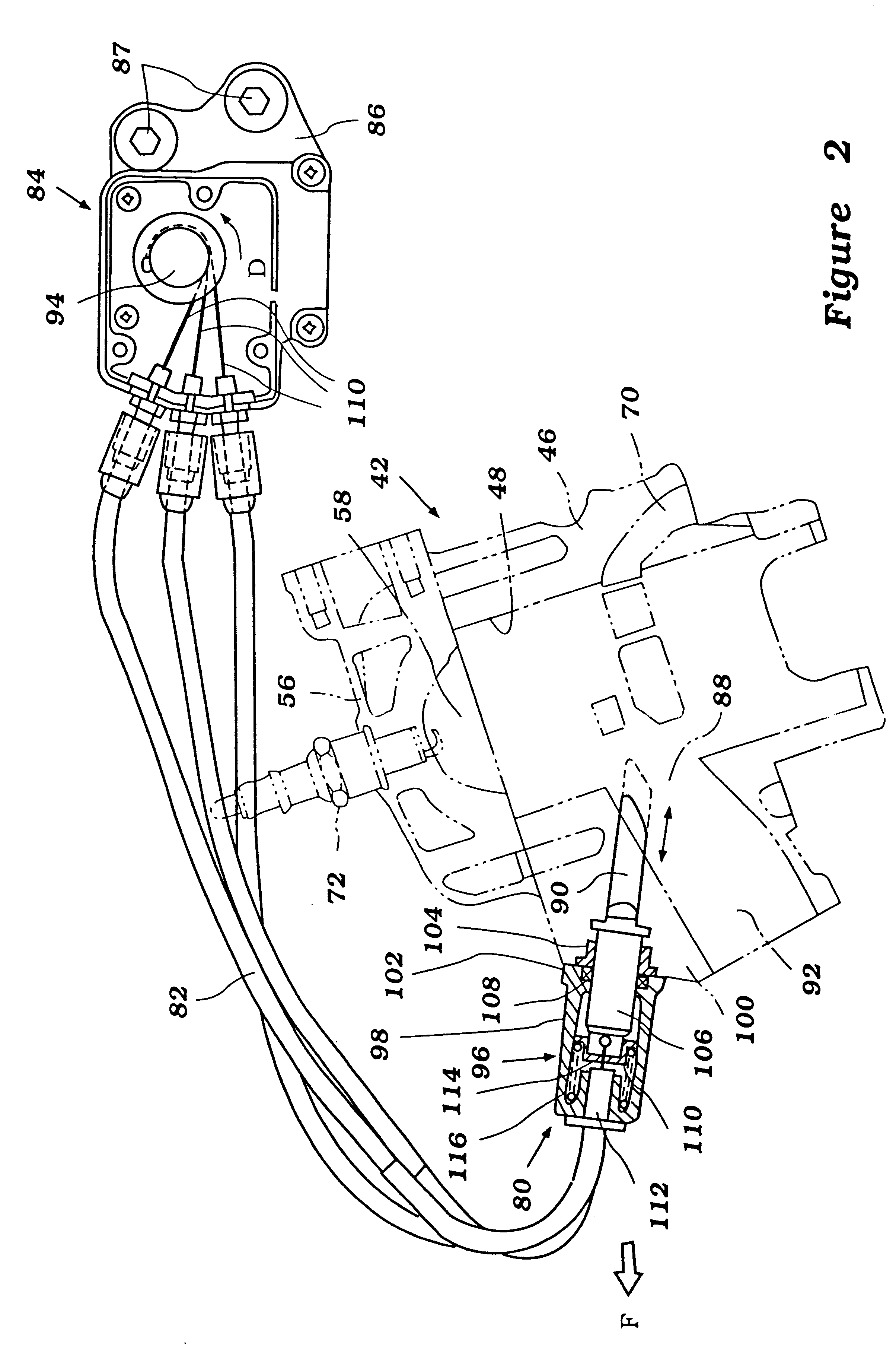
FIGS. 1 and 2 illustrate an exemplary watercraft 20. This environment is merely exemplary, as the present invention is useful with a variety of other watercraft and land vehicles. The watercraft 20 is desirably operated in a body of water designated by reference letter W. In use, the watercraft 20 is propelled through the body of water W in a forward direction, as designated by the arrow F in FIGS. 1 and 2. While being propelled forward, the personal watercraft 20 is capable of moving from the position shown in FIG. 1 to a planing position. The planing position is attained at a watercraft velocity associated with an engine speed referred to herein as "planing speed."

The watercraft body 24 generally comprises a hull 26 and a deck 28. A bond f...


PUM


Abstract

An engine has an exhaust control valve which is moved by a control system according to a predetermined control strategy. The control system obtains data from sensors that help the control system to identify certain characteristics of engine operating conditions. The control strategy involves cycling the exhaust control valve under predetermined engine operating conditions to clean the surface of the valve while reducing the impact of the cycling on engine performance. The cycling generally occurs during engine start-up and following engine shutdown. The cycling may be aborted during periods of rapid acceleration.

Description

1. Field of the InventionThe present invention generally relates to exhaust control valves for an engine. More specifically, the present invention relates to an exhaust control valve control arrangement that provides an exhaust valve cleaning mode which reduces the likelihood of such valves sticking as a result of use.2. Description of Related ArtConventional two-stroke engines generally include an exhaust port provided in each cylinder wall such that spent gases are exhausted through the exhaust port as the piston reciprocates in the cylinder. Exhaust port timing has an important effect on engine performance. Optimum exhaust port timing is dependent, in part, upon engine speed. For instance, to provide an improved engine performance, the exhaust port timing can be advanced during high-speed engine operation relative to the exhaust port timing during engine idling.One manner of controlling the exhaust port timing is to employ exhaust control valves. Generally, these valves are of th...

Claims


Application Information

Patent Timeline
Patent Type & Authority Patents(United States)
IPC IPC(8): F02D13/02F02P1/02F02B25/20F02D9/04F02D11/10F02D17/00F02D45/00
CPCF02D13/0249F02D13/0284Y02T10/18Y02T10/12
Inventor UCHIDA, YOSHIAKI
Owner YAMAHA MOTOR CO LTD
Learn More