Cathodic protection method and device for metal structure
- Summary
- Abstract
- Description
- Claims
- Application Information
AI Technical Summary
Problems solved by technology
Method used
Image
Examples
embodiment 1
(Embodiment 1)
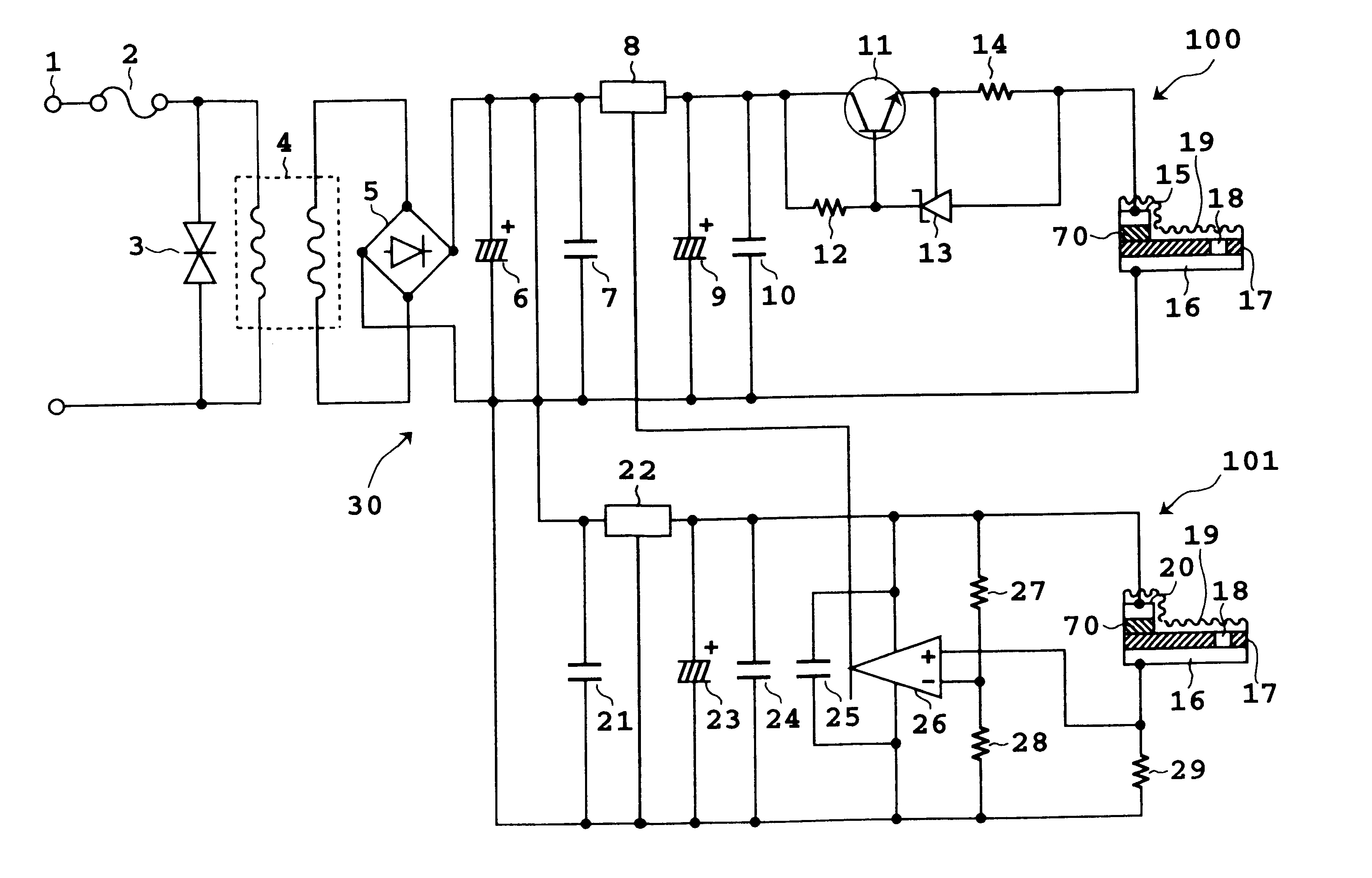
FIG. 8 is a circuit diagram of an apparatus suitable for achieving the cathodic protection method for a metal structure according to the present invention.
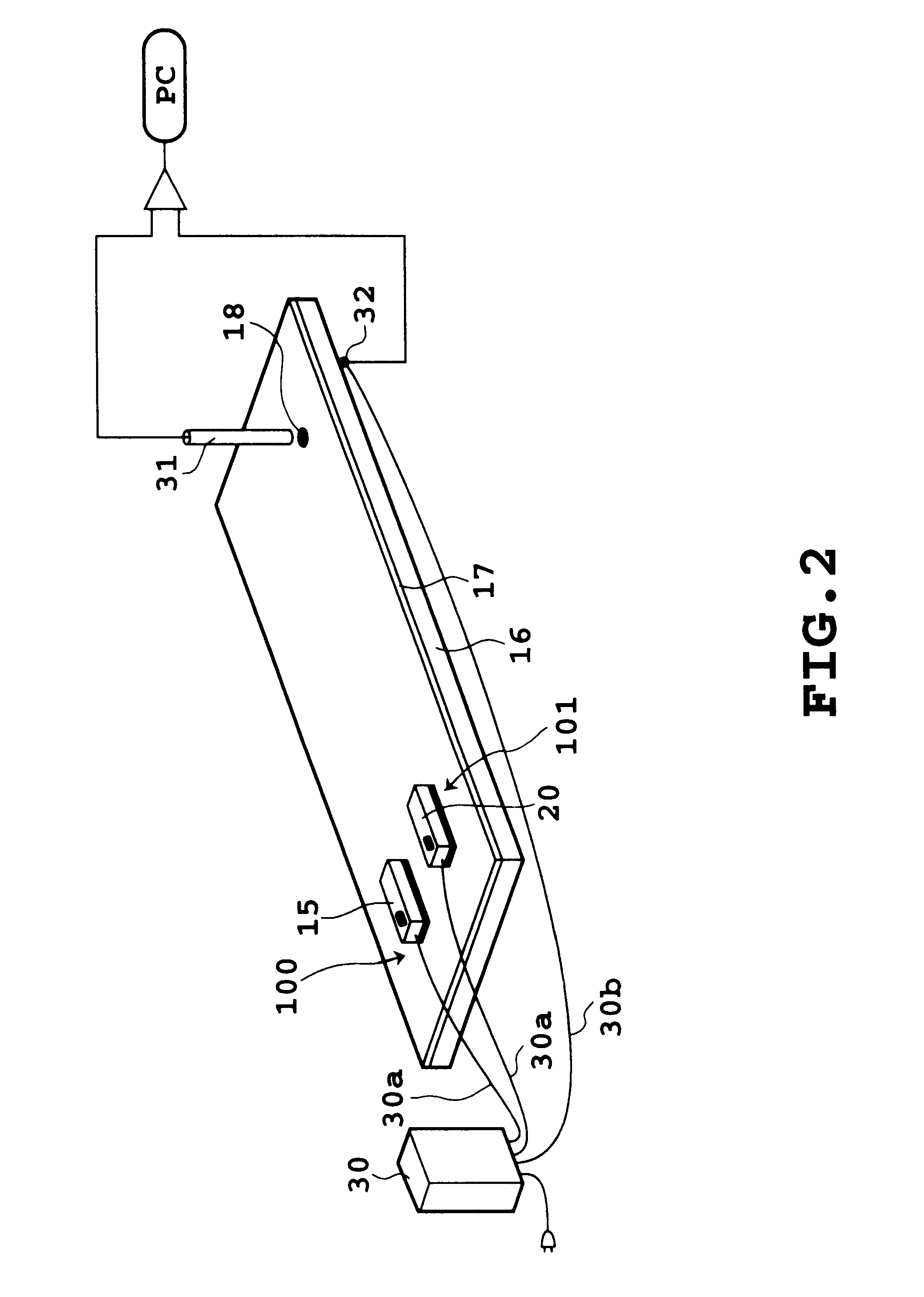
In the present method, a defective part 18 is in a coating film 17 of a coated steel plate 16 to be corrosion protected, and an anode 150 of such as made of aluminum or the like is bonded to the coated surface with an insulating two-sided bonding material 70. When the humidity is about 60%, a water film 19 covers the coated steel material 16, in which atmospheric pollution substances and sea salt particles dissolve to cause water constituting the water film to become an aqueous electrolyte solution, thus establishing a condition to generate a rust in the coating film defective part 18. To this condition, from a controller and the anode 150 according to the present invention, an optimum protection current is supplied to the coating film defective part 18 through the water film 19, thereby preventing rust generation in...
embodiment 2
(Embodiment 2)
The present embodiment is directed to a metal-made water pipe as the metal structure. In this apparatus, as shown in FIG. 10 and FIG. 11, a cathode 325 is mounted to an outer wall of the metal water pipe, an anode 324 is mounted to a flange disposed halfway the water pipe through a terminal 323, and a voltage applied between these parts is controlled by an electronic circuit which will be described later.
In this apparatus, output from an AC power supply 301 through a fuse 302 is stepped down by a transformer 304 to 15 to 40V. In the figure, 303 is a surge current absorption varistor. 305 is a rectifier circuit which coverts AC to DC. 306 and 307 are capacitors. 308 is a regulator which controls the voltage applied to the transistor 317 to a constant value. 309 and 310 are capacitors. 311 is a light emitting diode which displays input of electricity. 312 is a resistor for suppressing the current in the light emitting diode to a necessary minimum. 313 and 314 are output ...
embodiment 3
(Embodiment 3)
The present embodiment is a corrosion protection apparatus directed to a washing system comprising as a metal structure, as shown in FIG. 12, a washing tank 341 for washing vegetables or the like, a water pipe (water supply pipe) 342 for supplying water to the washing tank 341, and a drain pipe (waste pipe) 344 for draining water in the washing tank 341.
The stainless steel-made washing tank 341 is connected with a water supply pipe 342 and the drain pipe 344, an anode 346 same as the anode 324 in the above cathodic protection system shown in FIG. 10 and FIG. 11 is mounted to the water supply pipe 342, and a grounding band 347 is mounted to the drain pipe 344. A valve 345 is closed and a valve 343 is opened to supply water to the washing tank 341. In this state, a voltage is applied to the anode 346 and the cathode 347 through a wiring. As a result, not only the inner surface of the washing tank 341 which is exposed to various organic substances dissolved from plants an...
PUM
 Abstract
Description
Claims
Application Information
 - Generate Ideas
- Intellectual Property
- Life Sciences
- Materials
- Tech Scout
- Unparalleled Data Quality
- Higher Quality Content
- 60% Fewer Hallucinations
Browse by: Latest US Patents, China's latest patents, Technical Efficacy Thesaurus, Application Domain, Technology Topic, Popular Technical Reports.
© 2025 PatSnap. All rights reserved.Legal|Privacy policy|Modern Slavery Act Transparency Statement|Sitemap|About US| Contact US: help@patsnap.com


