
Compensated capacitive liquid level sensor

a capacitive liquid level sensor and capacitive technology, applied in variable capacitors, instruments, machines/engines, etc., can solve the problems of non-uniform electric field that interacts with liquid, erroneous basic capacitive level sensor, and relatively complicated construction

Inactive Publication Date: 2002-12-10
TAMAR SENSORS LTD
View PDF10 Cites 234 Cited by
  • Summary
  • Abstract
  • Description
  • Claims
  • Application Information

AI Technical Summary

Problems solved by technology

The basic capacitive level sensor gives an erroneous result if the dielectric constant of the liquid is other than the design value, or is unknown.
In the fringing-field type of capacitive sensor the electric field that interacts with the liquid is non-uniform.
1. Each of the two capacitors comprises spaced-apart plates, so the construction is relatively complicated since the plates must be isolated electrically, secured mechanically, and wired to the processing electronics.
2. Since the reference capacitor must be totally immersed in the liquid, an erroneous output is obtained for liquid levels lower than the reference capacitor height.
3. The practical requirement that the reference capacitor be located at the bottom of the container makes the measurement sensitive to contaminant liquids at the bottom of the container, since the measured dielectric constant is no longer representative of the intended liquid, for example water in a gasoline tank.
However, since the calculation is not simple, an analog-to-digital conversion, a microprocessor, and, possibly, a digital-to-analog conversion are necessary.
1. Since the fuel is separated from the electrodes by the thickness of the plastic wall (.di-elect cons. approximately 4), most of the field lines of force are shunted by the wall, and the sensor may respond unpredictably to the wall thickness, rather than to the presence of the fuel (.di-elect cons. approximately 1.8).
2. The DE invention attempts to correct this deficiency by independently sensing the dielectric constant of the wall, however, no compensation is made for the thickness variations of the wall.
3. No compensation is made for dielectric constant variations of the fuel such as that result from additions such as of alcoholic additives.
4. The electrodes being on the outside of the tank may respond to soil deposits that adhere to the electrodes, and to fuel splashed on the non-immersed portions of the electrodes.

Method used


Image

  • Compensated capacitive liquid level sensor
  • Compensated capacitive liquid level sensor
  • Compensated capacitive liquid level sensor

Examples


Embodiment Construction

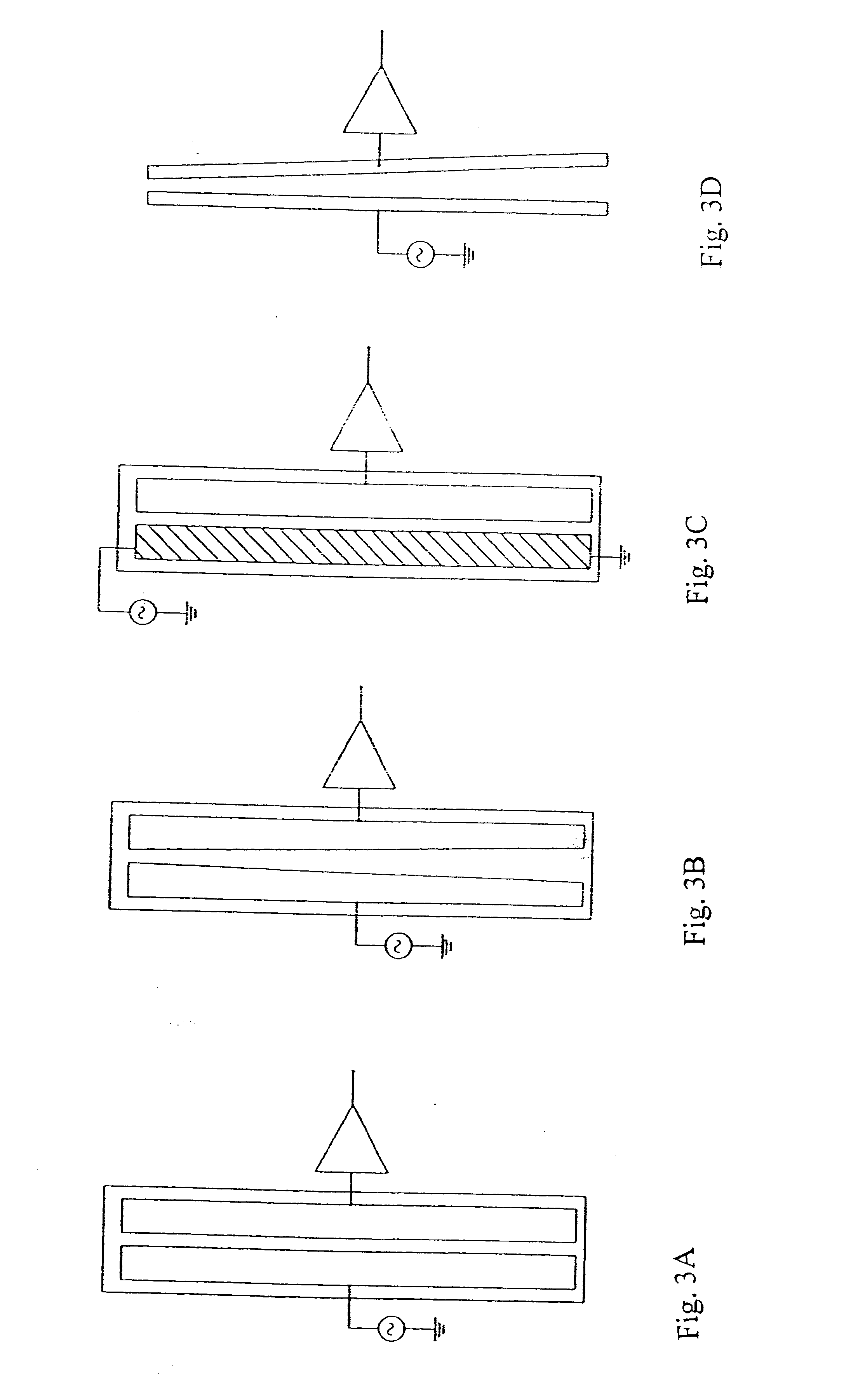
Referring now to the drawings, a first implementation of the coplanar primary capacitor with the dependence f(h) is shown in FIG. 3B, where the plates are separated by a gap that is substantially inversely proportional to the height h, as a result the capacitance per unit height is linearly proportional to the height.

A second implementation of the primary capacitor is shown in FIG. 3C. In this implementation the separation between the two plates is constant, however, one plate is printed using a conductive ink with a relatively high resistivity such as carbon ink. The bottom of this plate is grounded and the excitation is applied to its top, the plate thus serves as a distributed voltage divider, and the excitation voltage applied to each elemental capacitance is proportional to its height, the capacitive current thus behaves similarly to the previous case.

A third implementation of the primary capacitor is shown in FIG. 3D. This configuration is similar to the one in FIG. 3B in that...


PUM


Abstract

A fringing-field capacitive liquid level sensor comprising an electrically insulating substrate, having a first and a second pattern of conductive capacitance plates plated on the substrate. Each pattern constitutes a fringing-field capacitor having a capacitance the value of which is both dependent on the liquid level and dependent on the dielectric constant of the liquid. The ratio of the two capacitances, however, is proportional to the liquid level and independent of the dielectric constant of the liquid. The fringing-field capacitive liquid level sensor may be used for measurement of liquids of substantially any dielectric constant without requiring full-scale calibration or knowledge of, and calibration for, dielectric constant of the liquid to be measured. Compensation for tilt angle can be provided through the addition of a second level sensor.

Description

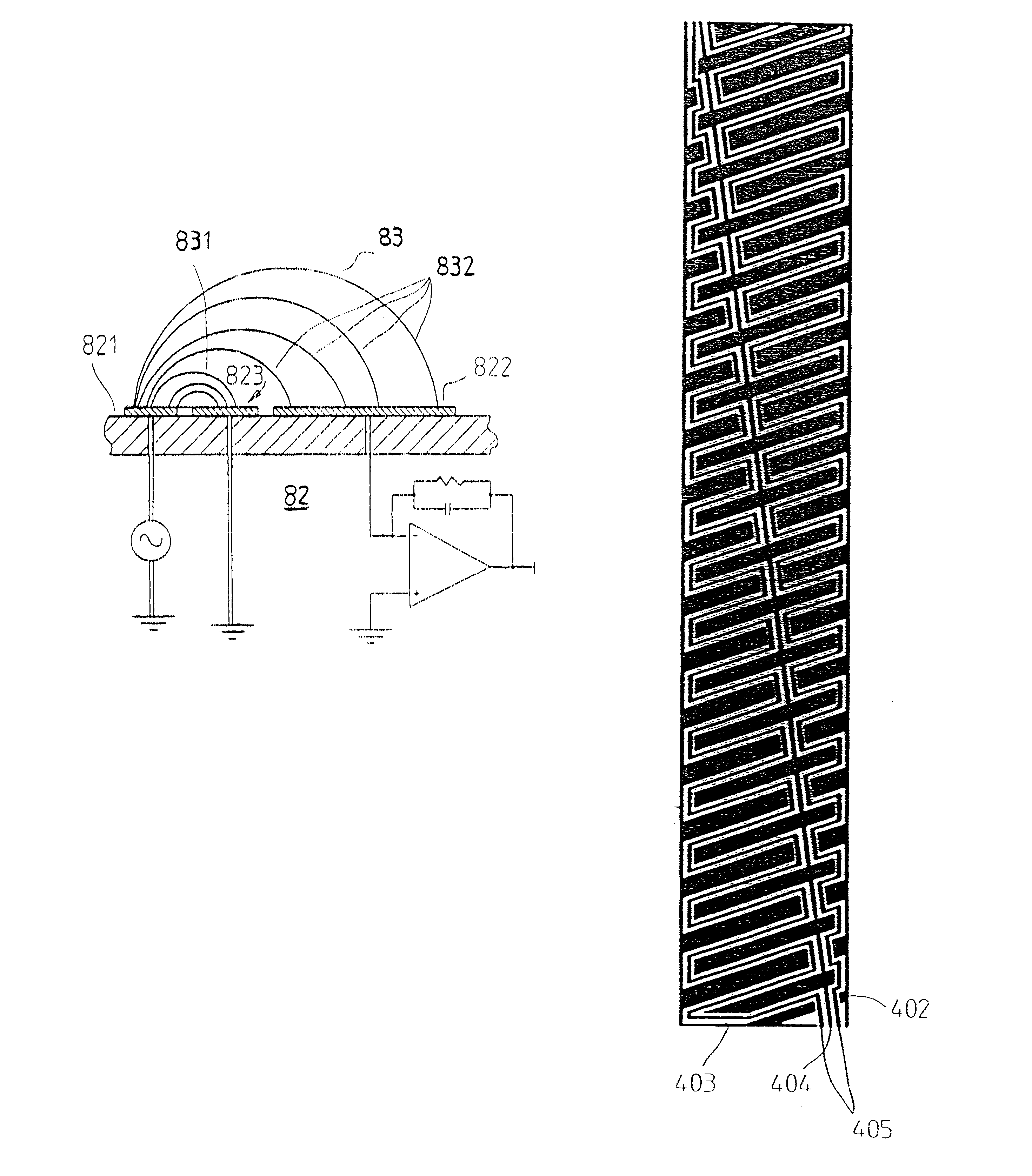
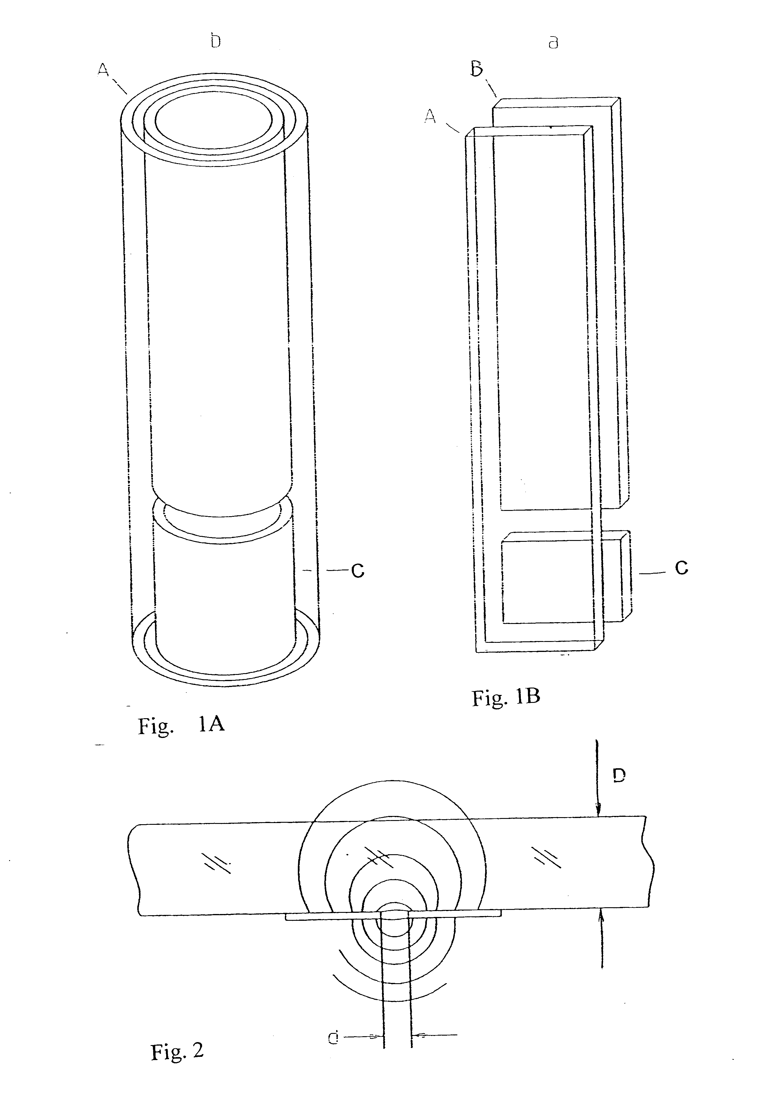
FIELD AND BACKGROUND OF THE INVENTIONThe present invention relates to a capacitive liquid level sensor, and more particularly, to a compensated capacitive liquid level sensor, which is insensitive to the dielectric constant of the liquid, the level of which is to be sensed. The resulting dielectric-constant-insensitive capacitive liquid level sensor has the advantage that prior knowledge of the liquid, the level of which is to be sensed, is not required. I.e., a particular vessel and sensor and sensing electronics may be provided, and used for virtually any desired liquid.Further, the liquid-level sensor of the present invention may also be employed as an inclinometer, measuring the tilt angle relative to gravity.1. General DescriptionIt was found by the inventor that a compensated capacitive liquid level sensor can be made, of the fringing-field type, i.e., where the capacitive plates are co-planar, and the effective "area" of the plates is essentially zero and the liquid interacts...

Claims


Application Information

Patent Timeline
Patent Type & Authority Patents(United States)
IPC IPC(8): G01C9/00G01C9/06G01C9/18G01F23/26G01F23/22G01C9/20
CPCG01C9/06G01C9/20G01F23/266G01F23/268G01C2009/062
Inventor NETZER, YISHAY
Owner TAMAR SENSORS LTD
Learn More