
Traveling-wave valve arrangement

a technology of traveling wave and valve arrangement, which is applied in the direction of electric discharge lamps, amplifiers with transit-time effect, amplifiers, etc., can solve the problem that the overall power loss of the valve arrangement that has to be discharged is increased

Inactive Publication Date: 2002-11-26
THALES ELECTRON DEVICES
View PDF8 Cites 13 Cited by
  • Summary
  • Abstract
  • Description
  • Claims
  • Application Information

AI Technical Summary

Benefits of technology

By employing an active cooling element and due to the power lost in the element, the power loss occurring in the valve arrangement that has to be discharged is in fact increased overall. However, the power loss component caused by the cooling element is low as compared to the power loss of the travelingwave valve, on the one hand, and any minor increase that may occur in the temperature of the housing of the valve due to the additional loss component is not critical, on the other hand.
The linearizer is usually arranged in an electromagnetically screened housing in order to avoid interference caused by leakage fields especially of the traveling-wave valve. In the arrangement as defined by the invention, the housing advantageously acts as an additional radiation barrier and heat insulator against the emission of heat from the valve located in the immediate proximity, or from a common housing of the valve arrangement that may enclose also the housing of the linearizer. By designing the inwardly and / or outwardly facing surfaces of the housing for low radiation emission or radiation absorption power for heat radiation, it is possible to further reduce heating of the linearizer via this path of radiation.
The linearizer is advantageously arranged near the radiation generating system and / or the signal input of the valve and far away from the collector of the valve, so that stronger radiation of heat into the linearizer due to the high temperature of the collector, as well as long signal paths from the linearizer to the signal input are avoided.

Problems solved by technology

By employing an active cooling element and due to the power lost in the element, the power loss occurring in the valve arrangement that has to be discharged is in fact increased overall.

Method used


Image

  • Traveling-wave valve arrangement
  • Traveling-wave valve arrangement

Examples


Embodiment Construction

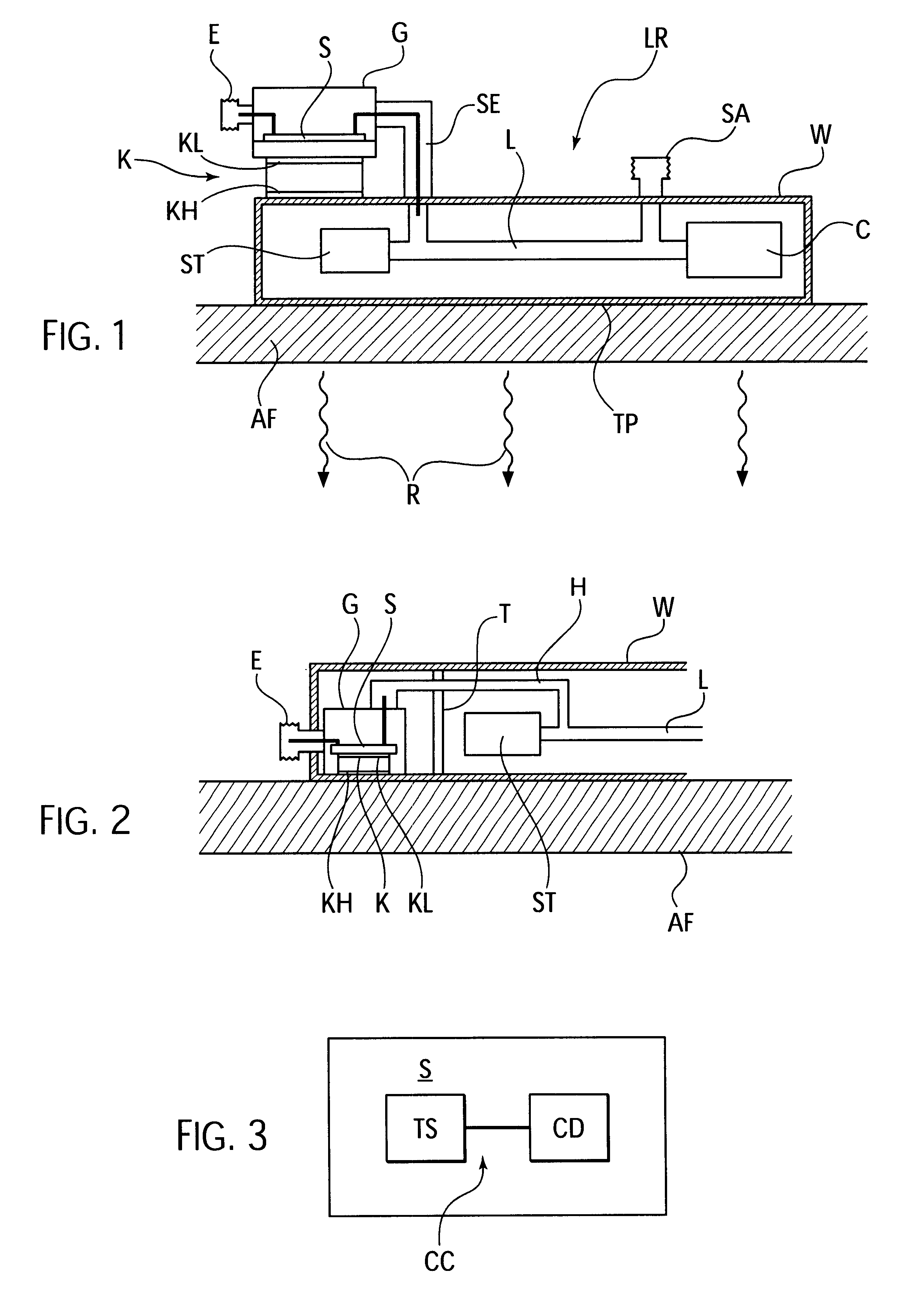
In the arrangement sketched in FIG. 1, a commonly used traveling-wave valve LR, which is surrounded by a stable wall, is secured with the surface of a wall on the heat-dissipating outer wall AF of a satellite. The heat emitted by the traveling-wave valve via its housing surface that is in contact with the satellite wall AF, is distributed in the outer wall AF of the satellite through solid-body heat conduction over a larger surface area, and primarily dissipated into outer space through the heat radiation R. The traveling-wave valve is in a typical way structured from a radiation generating system ST, a delay line L, and a collector C, and has a high-frequency signal input E and a signal output SA through the housing wall W. The interior structure of traveling-wave valves is known and of no importance to the invention in detail.

A cooling element K in the form of a Peltier element with a cooling surface KL that is cooler during operation, and with a warmer heat-emitting surface KH, i...


PUM


Abstract

For a traveling-wave valve arrangement with a traveling-wave valve and a linearizing circuit arrangement, it is proposed to design the linearizing circuit arrangement and the traveling-wave valve as one constructional unit and, for the thermal protection of the linearizing circuit arrangement in the simultaneous presence of a high permissible temperature of the valve housing, to maintain the circuit arrangement by means of an active cooling element at a nondamaging temperature lower than the one of the wall of the valve or of a common wall. The cooling element is preferably a Peltier element.

Description

The invention relates to a traveling-wave valve arrangement with a traveling-wave valve and a linearizing circuit arrangement.THE PRIOR ARTTraveling-wave valves are preferably employed as high-capacity amplifiers in the microwave range, and in particular in satellites. The power lost in the course of operation of such amplifier valves is dissipated as heat into the environment. When such valves are employed with satellites, the heat is dissipated into space through emission, whereby the housing of the valve is typically secured on the inner side of a heat-conducting wall section of the satellite, and the heat lost is dissipated via the housing of the valve into the wall section and emitted by the wall section. The emitting surface may become smaller as the temperature of the surface increases with no change in the emission power. A permissible minimum temperature of the housing of, for example, 100.degree. C. is therefore frequently required for the valves. The high component of pow...

Claims


Application Information

Patent Timeline
IPC IPC(8): H01J25/38H01J25/00H01J23/34H01J23/00
CPCH01J23/005H01J23/34H01J25/38
Inventor BRADATSCH, HUBERTPETERS, ANDREAS
Owner THALES ELECTRON DEVICES
Learn More