
Reduced-angle mammography device and variants

a mammography device and reduced angle technology, applied in the direction of instruments, patient positioning for diagnostics, applications, etc., can solve the problems of difficult to determine minor changes in tissues in early stages of a disease, patient pain and discomfort, and the above-described device has a relatively low sensitivity to radiation scattered in the immediate vicinity of the primary beam

Inactive Publication Date: 2002-11-19
QUANTA VISION
View PDF13 Cites 60 Cited by
  • Summary
  • Abstract
  • Description
  • Claims
  • Application Information

AI Technical Summary

Benefits of technology

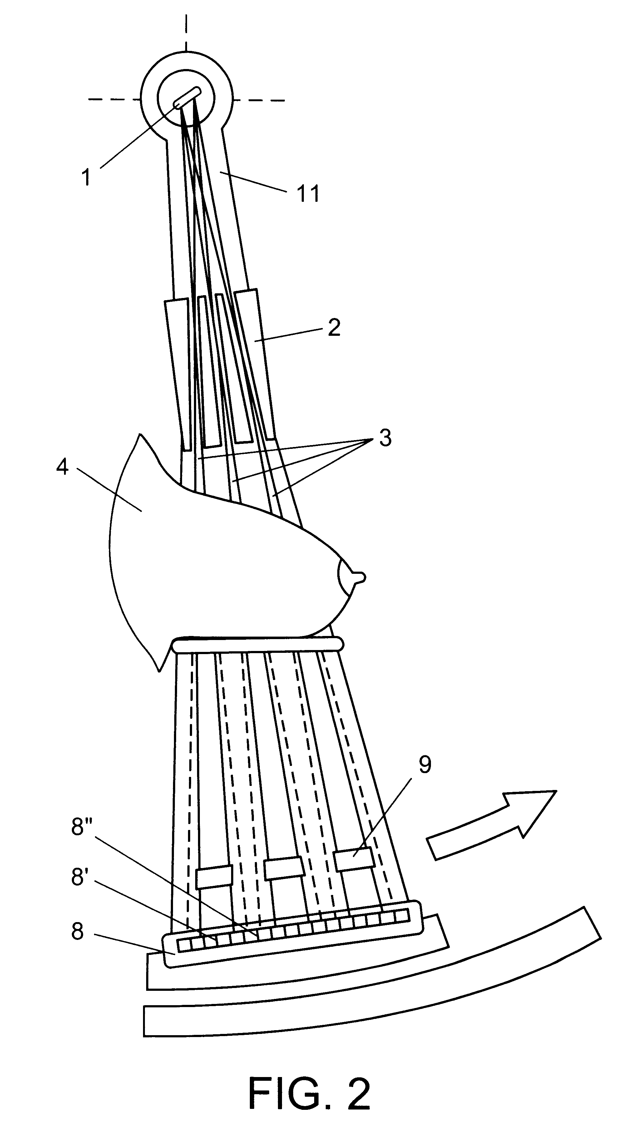
In any of the proposed embodiments, a collimator can be implemented in the form of one slit or in the form of a regular periodic structure being the radiation-transparent areas in the form of slits, and the opaque areas interleaved therewith. Use of a multi-slit collimator that forms a number of small-divergence beams allows a more efficient use of the source radiation. The rays formed by the collimator overlap a separate strip in the object projection. The spatial filter in this case is a collimator-like regular periodic structure, wherein the areas corresponding to the collimator transparent areas are made of a material opaque to a penetrating radiation such that the filter opaque areas overlap the collimator transparent areas. Further, size of slits, and structural period of the collimator, and size of transparent areas of the spatial filter must provide registration of only the radiation coherently scattered at small angles by the position-sensitive detector. The collimator must form the beams having a width and divergence providing the possibility to register the radiation scattered within a small-angle range, i.e. so that any ray scattered by an object at a small angle will transgress the primary beam boundaries in the registration zone. Further, the structural period of the collimator must by such that adjacent beams will not overlap one another in the detector plane. To register the source's primary radiation that passed through an object, additional elements of the position-sensitive detector are positioned on the filter opaque areas.
In any of the proposed embodiments, a translucent spatial filter that overlaps the radiation primary beam passed through an object and reduces its intensity at least to the level of the scattered radiation intensity preferably less than a number of times, can be used also. This will allow to improve sensitivity to the radiation scattered in immediate vicinity of the primary beam and, consequently, further reduce the patient irradiation dose.
An improvement of sensitivity to the radiation scattered in immediate vicinity of the primary beam can be attained by forming a beam having a sharp boundary and by an high precision of positioning of the spatial filter with respect to the collimator. For achieving this result, in the device, the collimator and spatial filter are implemented as a single unit whose entry portion facing the radiation source is a Kratky collimator having input and output diaphragms. The upper edge of the input diaphragm is situated in the plane that is common with the nether edge of the output diaphragm and the upper edge of the spatial filter; a free space is provided between the collimator and spatial filter, which space is intended for movement of an object.

Problems solved by technology

However, such compression results in that a patient feels a pain and discomfort.
As coefficients of absorption by the breast soft tissues have only a slight difference, so it is difficult to determine minor changes in tissues in early stages of a disease.
The above-described device has a relatively low sensitivity to the radiation scattered in immediate vicinity of the primary beam, because the primary beam radiation intensity considerably exceeds that of the scattered radiation and hinders the registration thereof.

Method used


Image

  • Reduced-angle mammography device and variants
  • Reduced-angle mammography device and variants
  • Reduced-angle mammography device and variants

Examples


Embodiment Construction

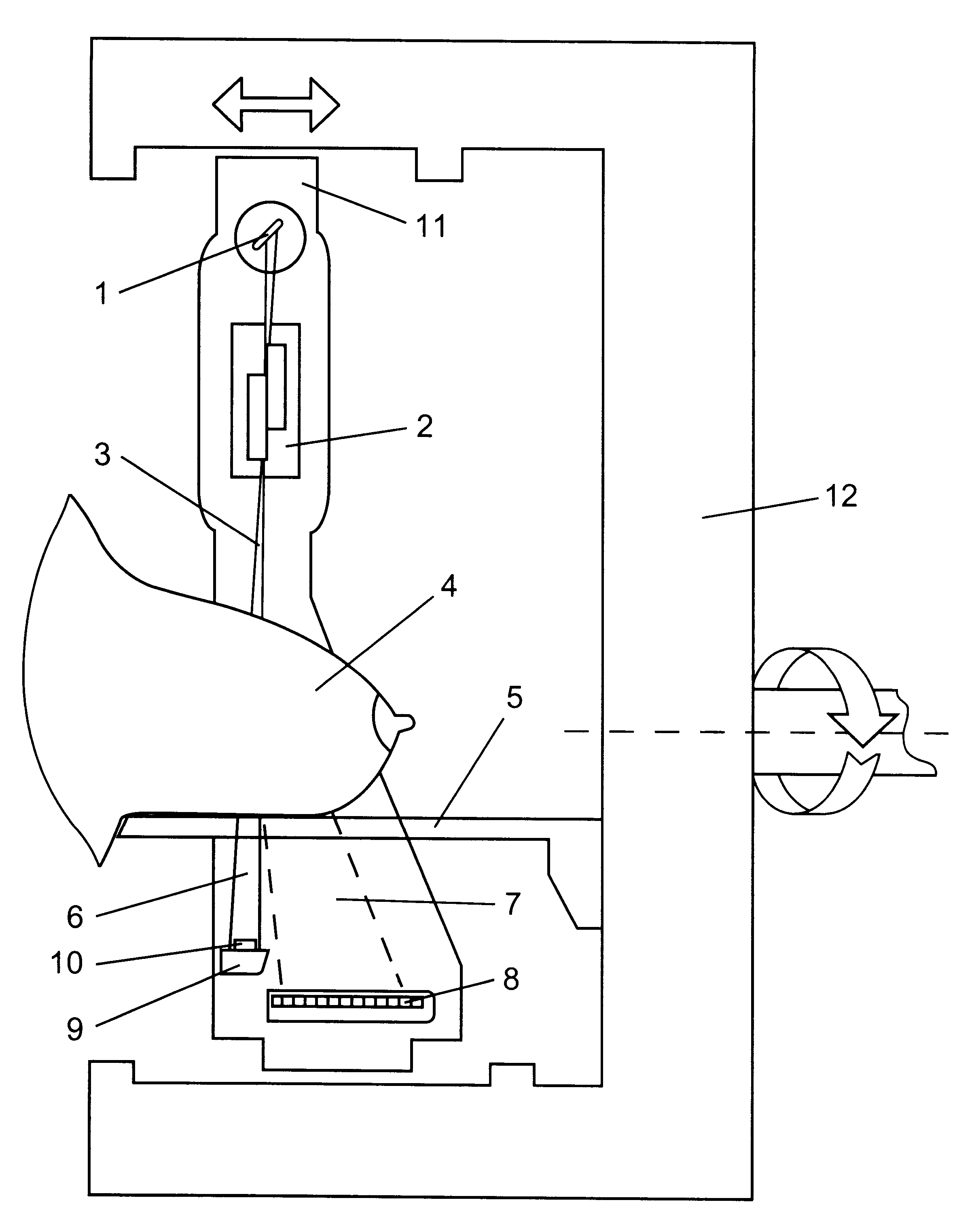
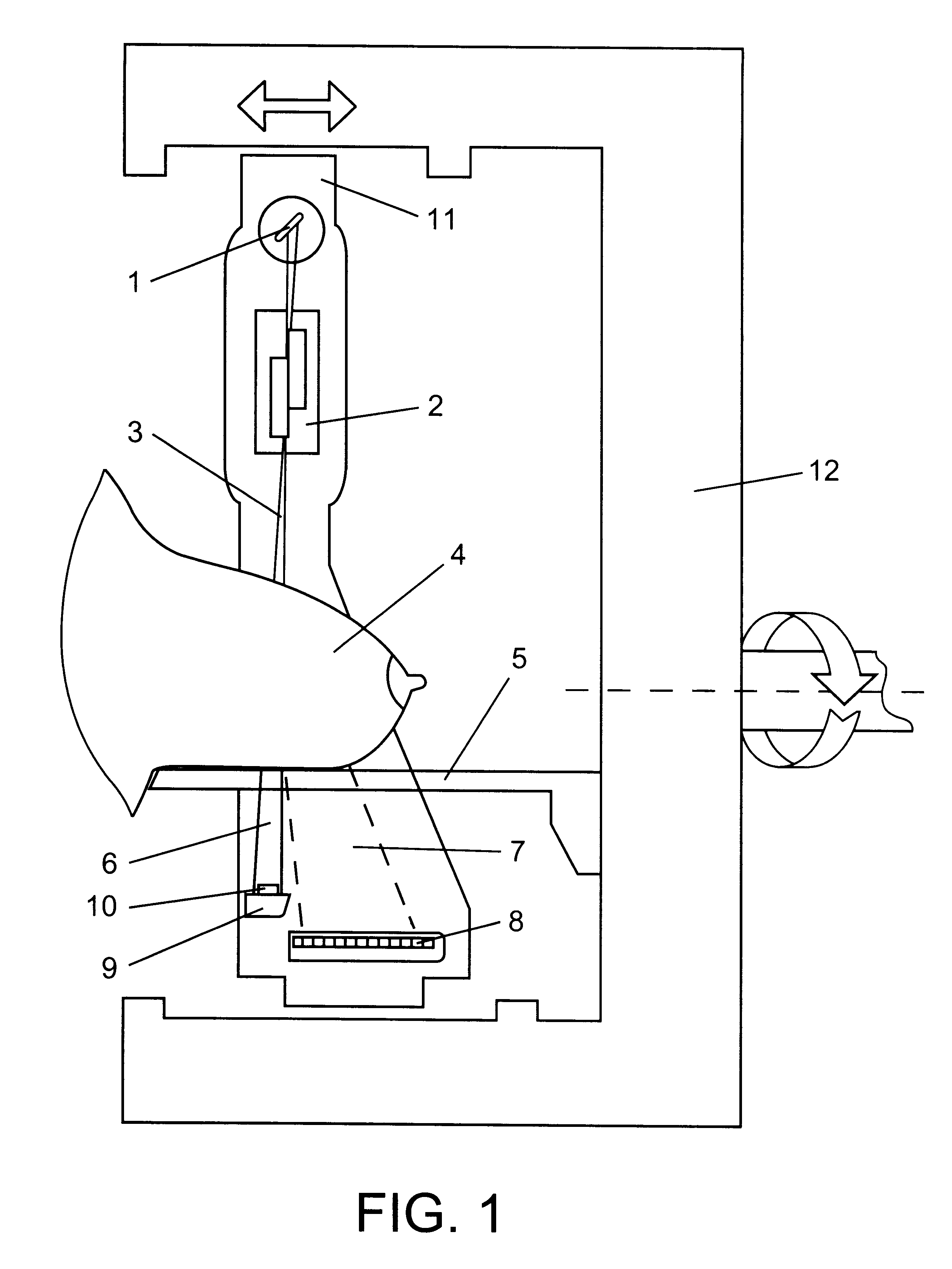
Devices are operated as follows. Radiation from source 1 of a penetrating radiation, for example, X-ray tube, is formed using collimator 2 into planar fan-shaped beam 3 (FIG. 1), or a number of fan-shaped beams (as in FIG. 2), and is directed to tested object 4 disposed on holder 5. On the path of the passed 6 through the object and scattered 7 radiation, positioned is position-sensitive detector 8 in the form of an array of radiation-sensitive elements intended for registration of the reduced-angle scattering, and also radiation-opaque filter 9 whereon positioned is detector 10 for registration of the radiation passed through the object. The registration system can be arranged in another way: filter 9 can be translucent, detector 10 can be disposed downstream of the filter. All instruments intended to form the radiation field and perform registration are disposed on frame 11 installed in turn on base 12. The frame on guides is moved in the direction normal to the radiation beam pla...


PUM


Abstract

The invention relates to the mammography devices based on registration of a reduced-angle coherently scattered radiation when an object is rayed by a penetrating radiation. Registration of the radiation coherently scattered by an object allows to produce an image of an object in the form of distribution of its structural characteristics. The device comprises a system for forming a directed on a tested object, narrow small-divergence beams, or a beam, having the same characteristics, and a system for extracting the radiation that is coherently scattered in small angles by an object. The invention proposes versions of a device that also provide for registration of the radiation passed through an object to make allowance for its thickness so that to obviate the necessity to compress the breast. The device allows to carry out relative movements of an object and system of irradiation-registration, as well as irradiate an object at different angles and by a number of radiation sources simultaneously. The possibility to register the coherently scattered radiation in ultra-small angles within the range of several angular seconds to 0.5 degree, and also the possibility to form the primary radiation beam having a sharp boundary are provided as well.

Description

The proposed invention relates to devices for producing an object image using reduced-angle scattering of a penetrating radiation, namely--to mammography devices that determine changes in the tissue structure. The invention can be suitably used in medical application for diagnosing the cancer cases of mammary glands at an early stage of a disease.PRIOR ARTThe known mammography devices are generally based on the principle that different substances, being subjected to raying, exhibit different properties of absorbing the X-ray radiation. The intensity of a radiation passed through an object and forming its projection image is determined by absorption property (absorption coefficient) of the substances constituting the object and by their thickness in the raying direction. To provide a quality image, it is necessary that a whole object would have the same thickness in the raying direction. The known devices provide said feature by compressing mammary gland to desired (or allowable) siz...

Claims


Application Information

Patent Timeline
IPC IPC(8): A61B6/02A61B6/00A61B6/06G01N23/02G01N23/04G21K5/10
CPCA61B6/0435A61B6/06A61B6/483A61B6/502G01N23/046G21K5/10G01N2223/419G01N2223/612
Inventor LAZAREV, PAVEL IVANOVICHKOMARDIN, OLEG VALENTINOVICH
Owner QUANTA VISION
Learn More