
Lithium secondary battery for use in electric vehicle

a secondary battery and electric vehicle technology, applied in secondary cell servicing/maintenance, emergency power supply arrangements, cell components, etc., can solve the problems of battery reducing the space utility of the vehicle, complex internal structure of the lamination type battery, and no clear idea on how to achieve the above concept using parameters

Inactive Publication Date: 2002-11-12
NGK INSULATORS LTD
View PDF5 Cites 23 Cited by
  • Summary
  • Abstract
  • Description
  • Claims
  • Application Information

AI Technical Summary

Problems solved by technology

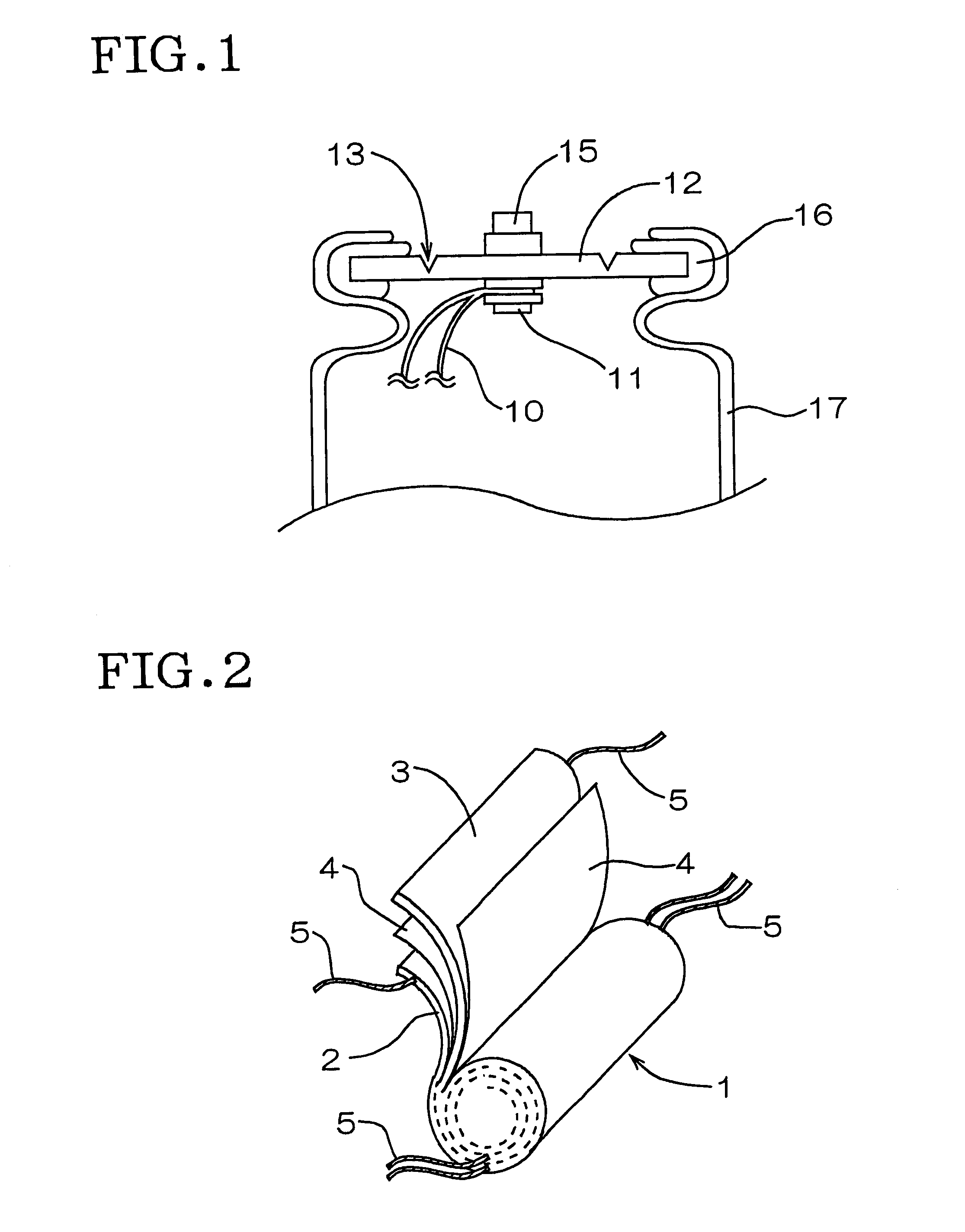
The lamination type battery, however, has a complicated internal structure for reasons such as the necessity of lead wire for each positive electrode and each negative electrode.
However, there is no clear idea yet on how the above concept is achieved using parameters, for example, the output, internal resistance, voltage drop and weight of the battery.
When the battery is allowed to have such a large volume that can produce an output necessary for giving sufficient acceleration, however, the volume of the battery reduces the space utility of the vehicle; the total vehicle weight becomes large and the efficiency of the battery becomes low; and an increase in battery cost raises the vehicle cost by that much.

Method used


Image

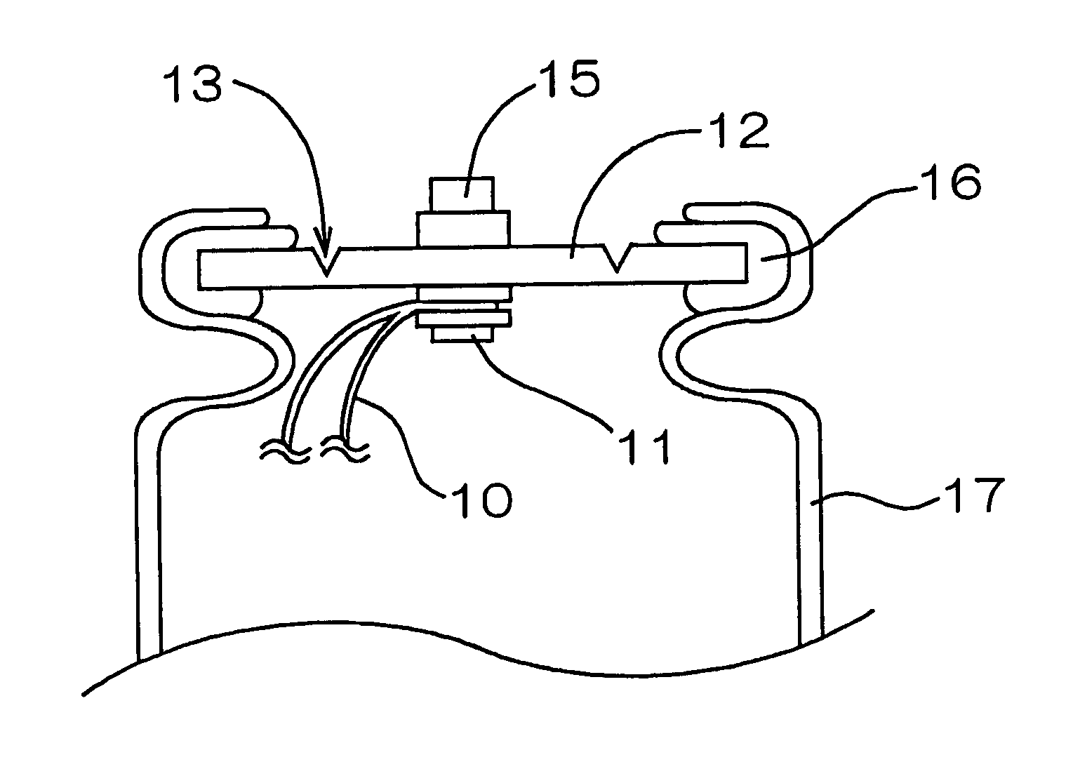
  • Lithium secondary battery for use in electric vehicle
  • Lithium secondary battery for use in electric vehicle

Examples


example 1

A positive electrode active material (LiMn.sub.2 O.sub.4) and a carbon powder (acetylene black) (this powder was for allowing the active material to have a higher conductivity) were mixed, and the resulting mixture was coated on an aluminum foil to produce a positive electrode having an electrode surface shape of 3,400 mm in length in the winding direction and 200 mm in width. Separately, a highly graphitized carbon material (a fibrous powder) was coated on a copper foil to produce a negative electrode of 3,600 mm in length in the winding direction and 200 mm in width. The positive electrode and the negative electrode were wound using, between them, a separator (an insulator) of 4,000 mm in length and 220 mm in width obtained by sandwiching a microporous polyethylene film capable of transmitting lithium ions with two same porous polypropylene films capable of transmitting lithium ions to form a three-layered structure, whereby an electricity-generating body was produced.

The electric...

example 2

A positive electrode active material [Li-rich lithium manganese oxide, Li(Li.sub.x Mn.sub.2-x)O.sub.4 (x=0.05)] and a carbon powder (acetylene black) (this powder was for allowing the active material to have a higher conductivity) were mixed, and the resulting mixture was coated on an aluminum foil to produce a positive electrode having an electrode surface shape of 3,600 mm in length in the winding direction and 100 mm in width. Separately, highly graphitized carbon material (a fibrous powder) was coated on a copper foil to produce a negative electrode of 4,000 mm in length in the winding direction and 100 mm in width. The positive electrode and the negative electrode were wound using, between them, a separator (an insulator) of 4,500 mm in length and 120 mm in width obtained by sandwiching a microporous polyethylene film capable of transmitting lithium ions with two same porous polypropylene films capable of transmitting lithium ions to form a three-layered structure, whereby an e...

example 3

A positive electrode active material [Li-rich lithium manganese oxide, Li(Li.sub.x Mn.sub.2-x)O.sub.4 (x=0.05)] and a carbon powder (acetylene black) (this powder was for allowing the active material to have a higher conductivity) were mixed, and the resulting mixture was coated on an aluminum foil to produce a positive electrode having an electrode surface shape of 5,600 mm in length in the winding direction and 50 mm in width. Separately, a highly graphitized carbon material (a fibrous powder) was coated on a copper foil to produce a negative electrode of 6,000 mm in length in the winding direction and 50 mm in width. The positive electrode and the negative electrode were wound using, between them, a separator (an insulator) of 6,500 mm in length and 70 mm in width obtained by sandwiching a microporous polyethylene film capable of transmitting lithium ions with two same porous polypropylene films capable of transmitting lithium ions to form a three layered structure, whereby an el...


PUM

PropertyMeasurementUnit
weightaaaaaaaaaa
terminal voltageaaaaaaaaaa
weightaaaaaaaaaa

Abstract

A lithium secondary battery for use in electric vehicle, includes: a battery case, and an electricity-generating body including a positive electrode, a negative electrode, and a separator, the positive and the negative electrode being wound or laminated via the separator so that the positive electrode and negative electrode are not brought into direct contact with each other. Each single battery has a ratio (X / E) of battery output X (W) and battery energy E (Wh), of 2 to 36 or a product (RxE) of battery internal resistance R (mOMEGA) and battery energy E (Wh), of 50 to 900 (mOMEGA.Wh). The lithium secondary battery is used in an electric vehicle as combined batteries formed by connecting a required number of the single batteries in series. The lithium secondary battery is designed so as to have a particular ratio of battery output and battery energy or a particular product of battery internal resistance and battery energy and thereby is capable of exhibiting performances necessary for electric vehicle, such as acceleration and the like when used as combined batteries obtained by connecting a required number of single batteries in series.

Description

BACKGROUND OF THE INVENTION AND RELATED ART STATEMENTThe present invention relates to a lithium secondary battery for use in electric vehicle. More particularly, the present invention relates to a lithium secondary battery suitably used as a battery for driving the motor of an electric vehicle (including a hybrid electric vehicle).In recent years, as the movement for environmental protection is increasingly becoming active, it has been investigated in the automobile industry to introduce, at a timing as early as possible, electric vehicles (EVs) or hybrid electric vehicles (HEVs) in place of conventional gasoline vehicles and the like using fossil fuels, and development of a battery used for driving of motor has become active because the battery is a key for practical use of electric car.As the battery for EV or HEV, a lithium secondary battery has drawn attention in recent years for the high energy density. This battery can therefore give a long running distance covered per one cha...

Claims


Application Information

Patent Timeline
Patent Type & Authority Patents(United States)
IPC IPC(8): H01M10/36H01M10/40H01M4/50H01M6/04H01M4/58H01M10/42H01M6/10H01M2/10H01M4/02H01M4/505H01M4/587H01M10/05H01M10/0525H01M10/0585H01M10/0587
CPCH01M4/505H01M10/0525H01M10/0587H01M2004/021H01M2010/4292Y02E60/122Y02T10/7011H01M4/587H01M6/10Y02E60/10Y02T10/70
Inventor NEMOTO, HIROSHIKITOH, KENSHIN
Owner NGK INSULATORS LTD
Learn More