
System and method for automatically selecting electrode polarity during sensing and stimulation

a technology of automatic selection and electrode polarity, applied in the direction of heart stimulators, heart defibrillators, therapy, etc., can solve the problems of simultaneous stimulation of left and right chambers, severe cardiac output perturbation, and limitations, and achieve optimal hemodynamic benefits for patients and improve coordination of heart chambers.

Inactive Publication Date: 2002-11-05
PACESETTER INC
View PDF24 Cites 178 Cited by
  • Summary
  • Abstract
  • Description
  • Claims
  • Application Information

AI Technical Summary

Benefits of technology

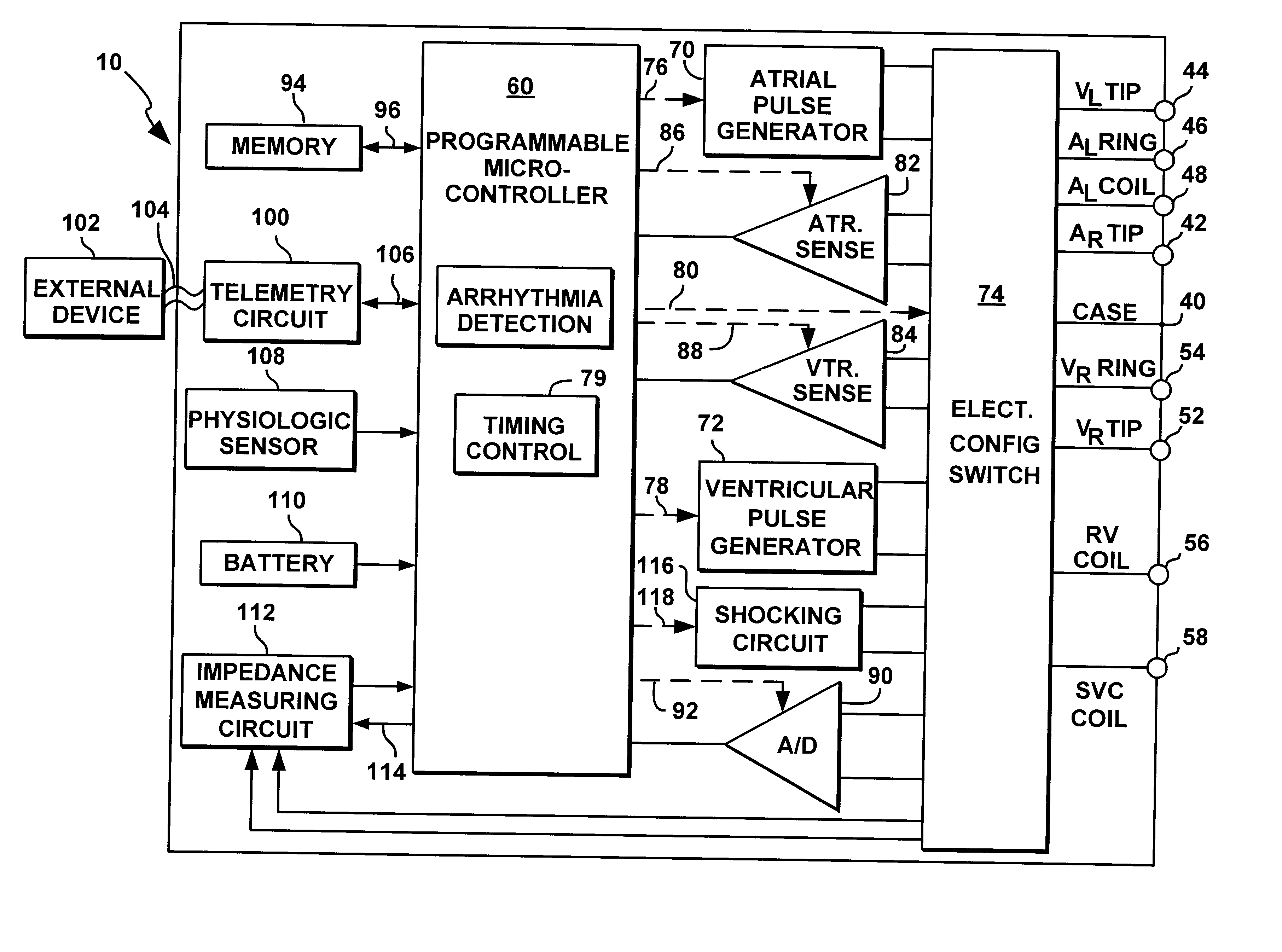
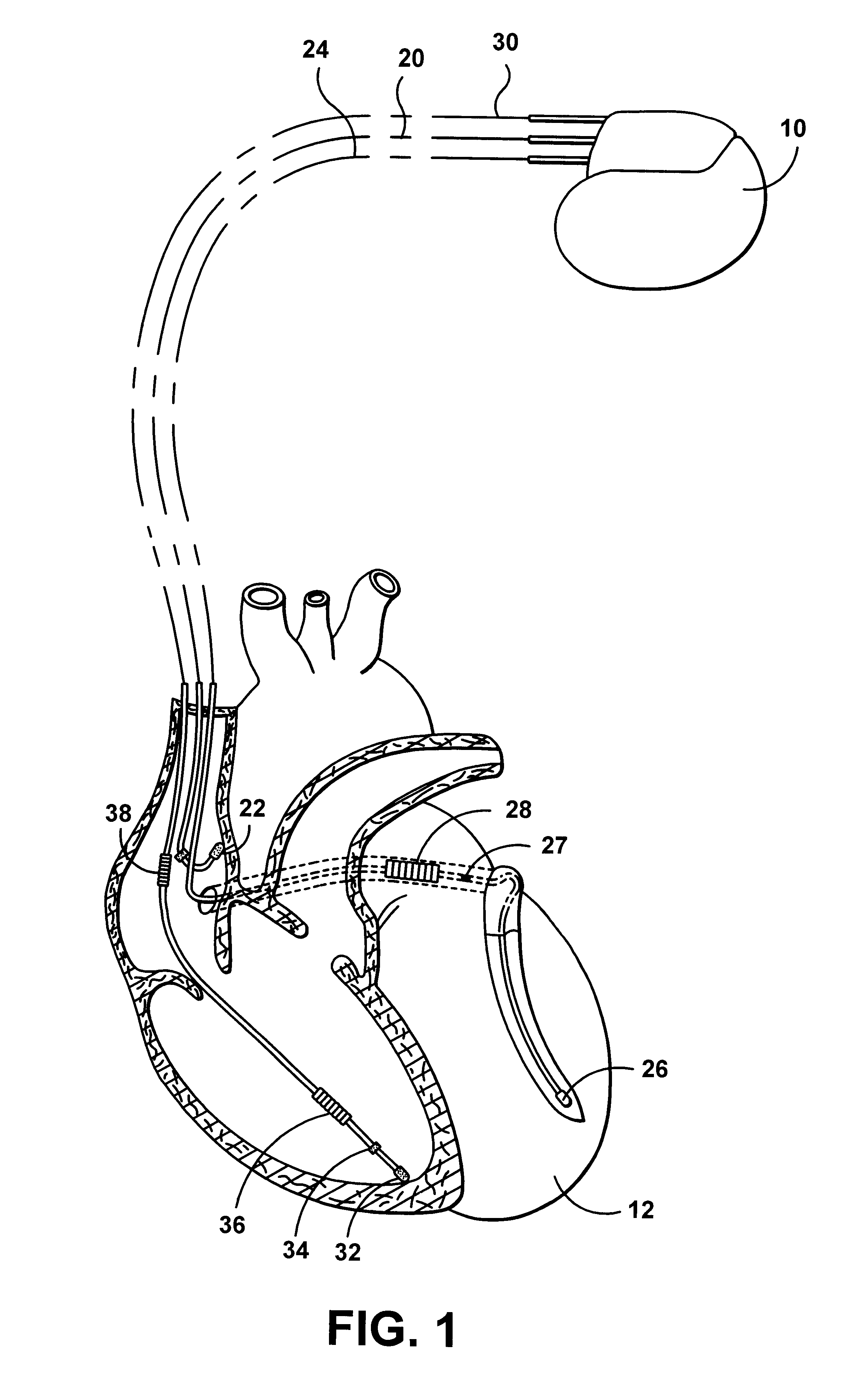
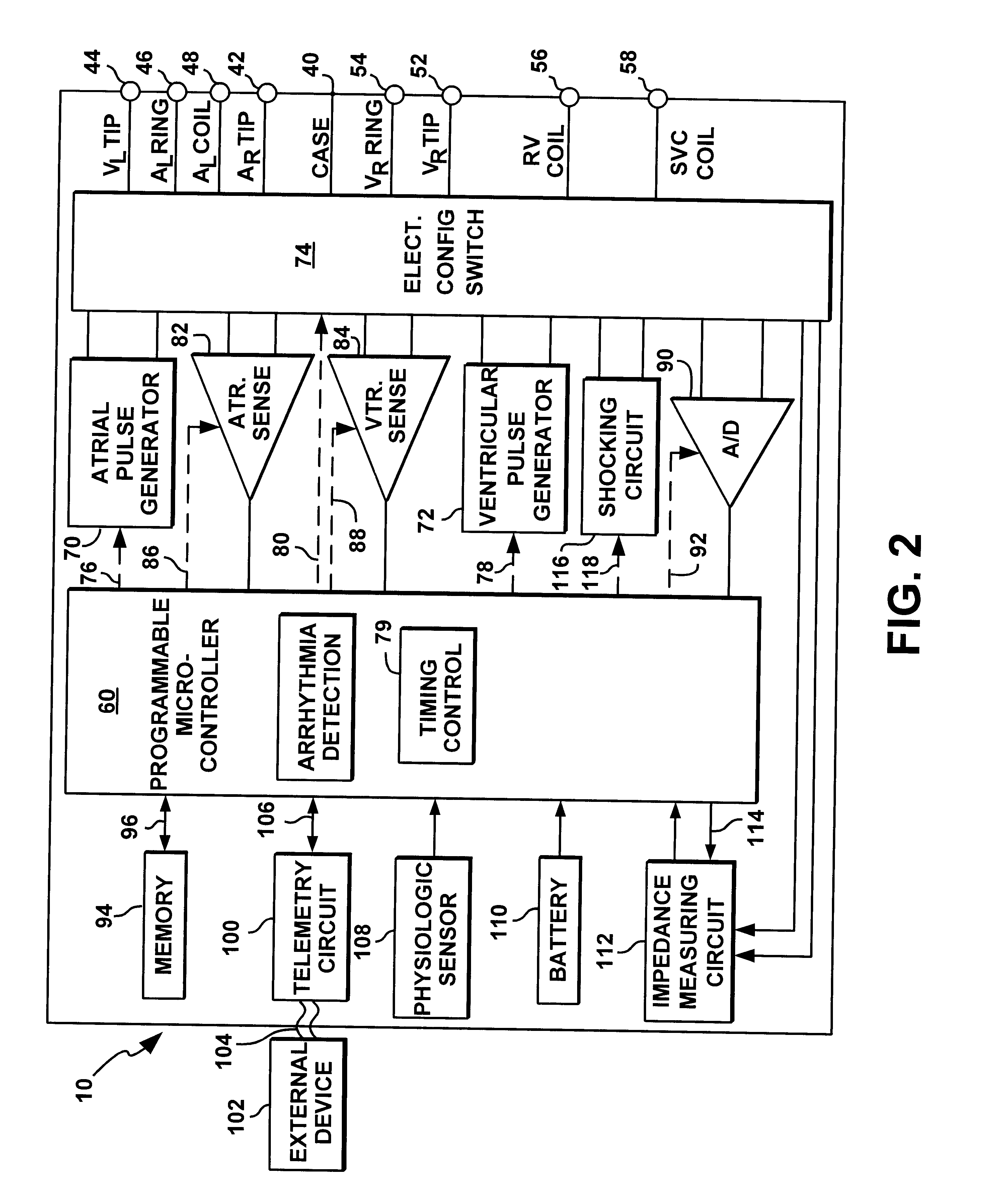
The present invention addresses this need by providing an implantable multichamber or multisite cardiac stimulation device in which the electrode configurations for sensing and stimulation are flexibly programmable, and the stimulation sequence between multiple sites can be precisely controlled.
Yet another aspect of the present invention is the ability to program unique coupling intervals for precisely controlling the activation sequence of stimulated sites. Coupling intervals may be defined in relation to the originating location of a detected depolarization or in relation to stimulus delivery at another location. Coupling intervals are advantageously selected in a way that provides optimal hemodynamic benefit to the patient by overcoming various conduction disorders or improving coordination of heart chambers in patients suffering from heart failure. One embodiment of the present invention includes a method for automatically determining the optimal coupling intervals and adjusting the programmed settings based on measurements related to the hemodynamic state of the heart.

Problems solved by technology

In this way, simultaneous bi-atrial or simultaneous bi-ventricular pacing is achieved via bipolar stimulation but with several limitations.
Firstly, this configuration of bipolar stimulation is distinctly different from a conventional bipolar lead configuration wherein both the cathode and anode are located a short distance apart, approximately one centimeter, on the same lead.
A potential risk that exists when higher output settings are used, as may be needed to ensure bi-chamber stimulation, is cross-chamber capture, also known as cross-stimulation (Ref: Levine PA, et al., Cross-stimulation: the unexpected stimulation of the unpaced chamber, PACE 1985: 8: 600-606).
Such cross-chamber capture is a highly undesirable situation in that the upper and lower chambers would contract against each other causing severe cardiac output perturbation.
Another limitation of the multi-chamber stimulation systems described above is that simultaneous stimulation of left and right chambers, as required when two leads are coupled together by one adapter, is not always necessary nor desirable.
In this case, stimulation of both chambers simultaneously would be wasteful of battery energy.
Another limitation is that, in the presence of an inter-atrial or inter-ventricular conduction defect, one may want to control the interval between a sensed or paced event in one chamber and delivery of a stimulation pulse to the other chamber.
Yet another limitation is that, once implanted, the designation of cathode and anode assignments is fixed and cannot be reassigned in order to determine the polarity that results in the lowest stimulation thresholds, to achieve a desired directionality of the stimulation delivery or to obtain the optimal sequencing of stimulation and / or sensing to optimize hemodynamic function.
In some patients, a lower stimulation threshold or an improved excitation pattern or perhaps even hemodynamic benefit might be achieved by reversing the cathode and anode locations yet this cannot be done without operative intervention.
In the first generation of multi-chamber devices, an adapter was required to connect multiple leads to a conventional dual chamber device, a requirement that adds cost and time to the implant procedure.
Adapters can be cumbersome and an additional site for potential lead breakage or discontinuity, essentially adding bulk and a "weak link" to the implanted system.
While this design advantageously eliminates the need for adapters, the hardwire connections preclude the potential to non-invasively adjust the polarity orientation.
U.S. Pat. No. 5,720,518 does not address the ability to control the interval between detection and stimulation within the atria or ventricles in the setting of multisite stimulation.
While the duration of the conduction delay window can be programmed, no method is provided by which to select the optimal interval between chamber depolarizations.
Patients with hemodynamic abnormalities often have conduction defects due to dilation of the heart or other causes.

Method used


Image

  • System and method for automatically selecting electrode polarity during sensing and stimulation
  • System and method for automatically selecting electrode polarity during sensing and stimulation
  • System and method for automatically selecting electrode polarity during sensing and stimulation

Examples


Embodiment Construction

The following description is of a best mode presently contemplated for practicing the invention. This description is not to be taken in a limiting sense but is made merely for the purpose of describing the general principles of the invention. The scope of the invention should be ascertained with reference to the issued claims. In the description of the invention that follows, like numerals or reference designators will be used to refer to like parts or elements throughout.

The present invention relates to a cardiac stimulation device capable of delivering precisely ordered stimulation pulses to multiple chambers of the heart, referred to herein as multi-chamber stimulation, or to multiple sites within a chamber of the heart, referred to herein as multi-site stimulation. As used herein, the shape of the stimulation pulses is not limited to an exact square or rectangular shape, but may assume any one of a plurality of shapes which is adequate for the delivery of an energy pulse, packet...


PUM


Abstract

An implantable multi-chamber cardiac stimulation device includes flexibly programmable electrode stimulation configurations, and is capable of precisely controlling the stimulation sequence between multiple sites. The stimulation device provides a plurality of connection ports that allow independent connection of each electrical lead associated with a particular stimulation site in the heart. Each connection port further provides a unique terminal for making electrical contact with only one electrode such that no two electrodes are required to be electrically coupled. Furthermore, each electrode, whether residing on a unipolar, bipolar or multipolar lead, may be selectively connected or disconnected through programmable switching circuitry that determines the electrode configurations to be used for sensing and for stimulating at each stimulation site. The stimulation device allows for the programmable selection of each electrode terminal connection to a relatively positive or negative battery potential. In this way, each electrode, when electrically connected, may be programmed to act as the cathode or as the anode during sensing or stimulation delivery. Thus, directionality of the depolarization wave may be controlled by programming the cathode and anode assignments of the stimulation electrodes.

Description

FIELD OF THE INVENTIONThis invention relates generally to programmable cardiac stimulating devices. Specifically, the present invention is directed to an implantable stimulation device and associated method for controlling the electrode sensing and stimulation configurations and the activation sequence in a multi-chamber cardiac stimulation device using noninvasive programming techniques. More particularly, the stimulation device allows for a programmable selection of each electrode terminal connection to a relatively positive or battery potential. In this way, each electrode, when electrically connected, may be programmed to act as a cathode or as an anode during sensing or stimulation delivery. Thus, directionality of the depolarization wave may be controlled by programming the cathode and anode assignments of the stimulation electrodes.BACKGROUND OF THE INVENTIONIn a normal human heart, the sinus node, generally located near the junction of the superior vena cava and the right at...

Claims


Application Information

Patent Timeline
IPC IPC(8): A61N1/362A61N1/368A61N1/39
CPCA61N1/3627A61N1/368A61N1/3684A61N1/3918A61N1/36843
Inventor LEVINE, PAUL A.
Owner PACESETTER INC
Learn More