
Flash gas and superheat eliminator for evaporators and method therefor

a technology of flash gas and superheat, which is applied in the direction of mechanical equipment, refrigeration components, lighting and heating apparatus, etc., can solve the problems of reducing the volumetric efficiency of the compressor, the actual refrigeration cycle may deviate from the ideal cycle, and the flash gas loss region and the superheat region of the evaporator are less effective at removing hea

Inactive Publication Date: 2002-10-08
OLIVE TREE PATENTS 1 +1
View PDF5 Cites 68 Cited by
  • Summary
  • Abstract
  • Description
  • Claims
  • Application Information

AI Technical Summary

Benefits of technology

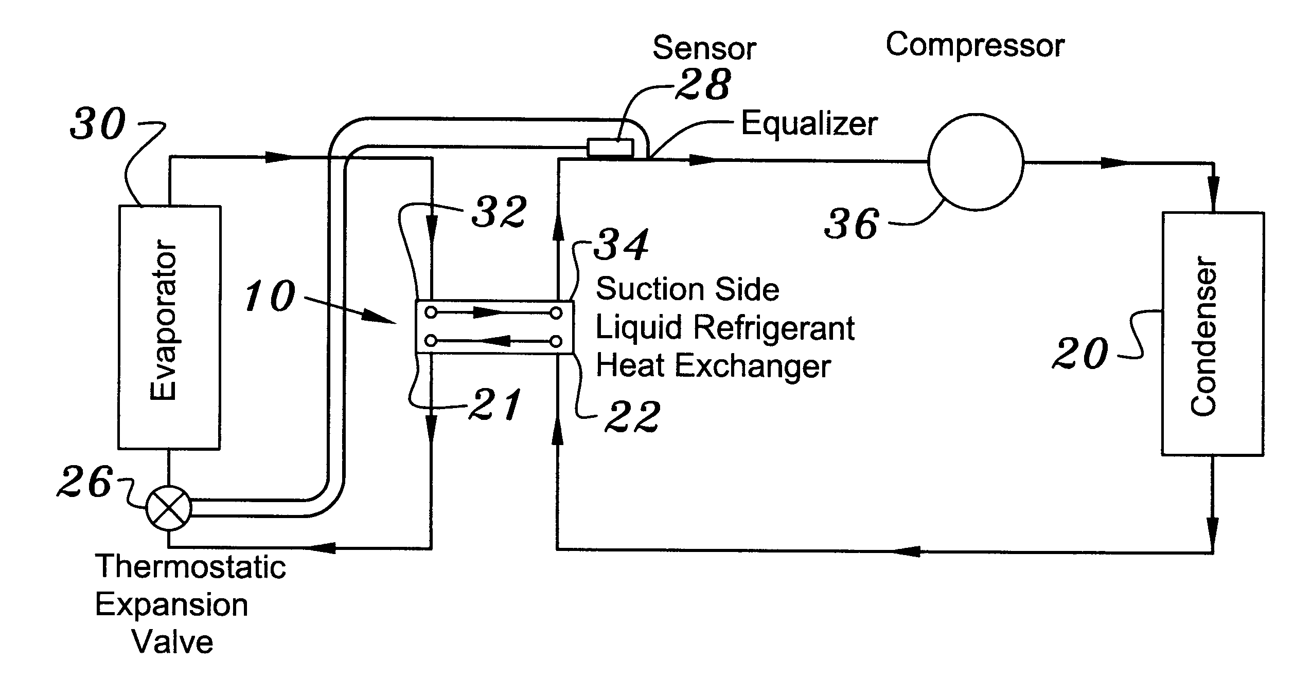
The present invention is defined by the appended claims with the specific embodiment shown in the attached drawings. The present invention is directed to an apparatus and system that satisfies the need for increased refrigeration capacity in any kind of refrigeration system and increased dehumidification in air cooling systems as well as increased capacity and efficiency of any type of heat producing heat pump refrigeration system.
Moreover, the present invention provides such a cold liquid refrigerant to the TXV that flash gas loss in the evaporator is minimized or eliminated thereby increasing the effective evaporator surface area. Also, the superheat region of the evaporator is eliminated by the present invention so that the effective evaporator surface area is increased even more. Because of the increased effective surface area of the evaporator, a significant increase in refrigerant mass flow through the evaporator is accomplished thereby increasing the refrigeration capacity of the system.
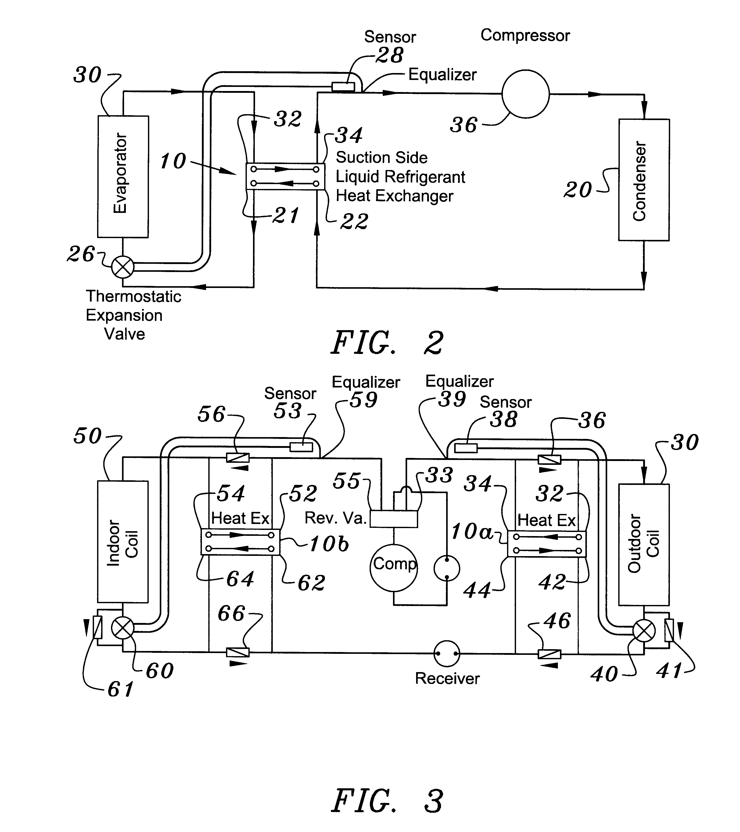
Further, where heating is the primary function of the refrigeration system, such as in a heat pump heating cycle, the heating capacity is increased both by the improved heat absorption capacity of the evaporator as well as by the heat reclaim of liquid refrigerant heat in the low pressure, suction side to liquid refrigerant heat exchanger.
An important feature of the present invention is that the increased mass flow of refrigerant through the evaporator also increases the volumetric efficiency of the compressor, thereby increasing the overall system efficiency.

Problems solved by technology

However, the actual refrigeration cycle may deviate from the ideal cycle primarily because of pressure drops associated with the fluid flow and heat transfer to or from the surroundings.
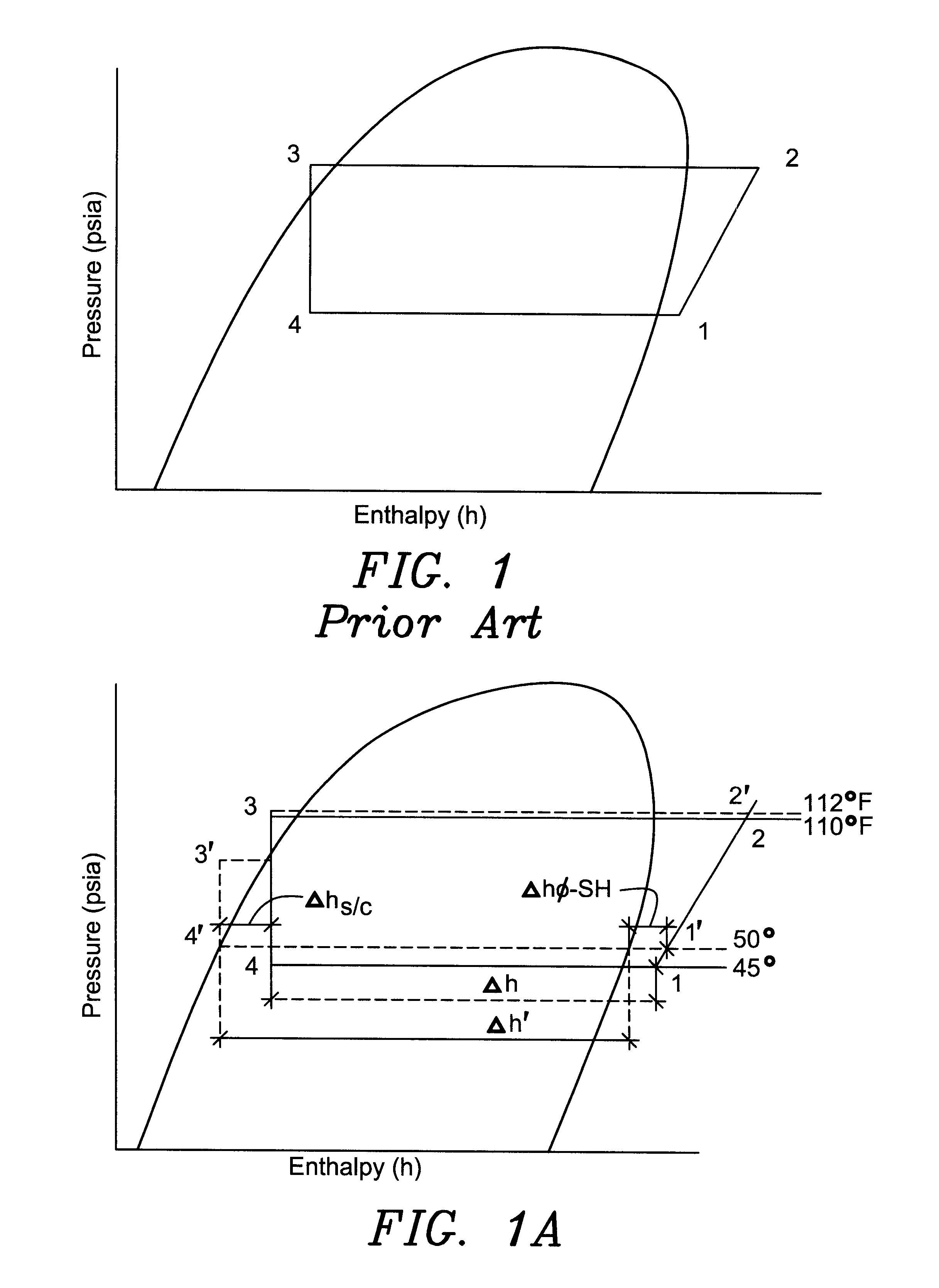
Both the flash gas loss region and the superheat region of the evaporator are less effective at removing heat than the phase change area.
In fact, the colder the refrigeration application the greater the effect of this elimination of the flash gas loss and superheat regions.
The problem with these known heat exchangers are that this increased superheat temperature reduces the volumetric efficiency of the compressor, increases the hot gas discharge temperature, increases the operating temperature of the compressor thereby decreasing the operational life expectancy of the compressor and only minimally affects the liquid refrigerant temperature because of the limited effectiveness of using superheat only to cool the liquid refrigerant.

Method used


Image

  • Flash gas and superheat eliminator for evaporators and method therefor
  • Flash gas and superheat eliminator for evaporators and method therefor
  • Flash gas and superheat eliminator for evaporators and method therefor

Examples


Embodiment Construction

that follows is offered so that the present contribution to the art can be more fully appreciated. Additional features of the invention will be described hereinafter. These form the subject of the claims of the invention. It should be appreciated by those skilled in the art that the conception and the disclosed specific embodiment may be readily utilized as a basis for modifying or designing other structures for carrying out the same purposes of the present invention. It should also be realized by those skilled in the art that such equivalent constructions do not depart from the spirit and scope of the invention as set forth in the appended claims.

For a more succinct understanding of the nature and objects of the present invention, reference should be directed to the following detailed description taken in connection with the accompanying drawings in which:

FIG. 1 is a representation of the refrigeration process on a pressure enthalpy diagram;

FIG. 1a is a pressure enthalpy diagram sh...


PUM


Abstract

A low pressure suction side refrigerant to liquid refrigerant heat exchanger, located in the refrigeration circuit in such a way that the sensor (and external equalizer tube, if applicable) is located downstream of the low pressure refrigerant outlet of the heat exchanger, provides for effectively eliminating both the superheat and flash gas loss regions of the evaporator which in turn increases the mass flow through the evaporator and increases the refrigerating capacity of the evaporator at very little increase in compressor power thereby providing for increased system efficiency for refrigerating or cooling purposes. On the heating side, heat rejection capacity of a heat pump is increased even more dramatically because of the heat reclaim of the flash gas loss heat, which provides for even greater efficiency increases for heating applications.

Description

1. Field of the InventionThe present invention relates to a refrigerant suction side to liquid refrigerant heat exchanger located in such a way that the sensing bulb of a thermostatic expansion valve (TXV) whether mechanical or electronic, is located downstream of the heat exchanger, which is in turn downstream of the evaporator, in the direction of flow of the suction gas towards the compressor, so that the preset superheat setting of the thermostatic expansion device / valve is not exceeded by the action of the heat exchanger.This invention more particularly pertains to the heat exchanger reducing or eliminating both the flash gas loss and superheat regions of an evaporator, thereby increasing the effective surface area of an evaporator and providing for a colder average temperature of the evaporator and providing for an increased mass flow of refrigerant through the evaporator and thereby an increased heat absorbing capacity of the evaporator.Where the primary function of the refri...

Claims


Application Information

Patent Timeline
IPC IPC(8): F25B13/00F25B40/00F25B41/04
CPCF25B13/00F25B40/00F25B41/04F25B2600/2513F25B2700/21151
Inventor HEBERT, THOMAS H.
Owner OLIVE TREE PATENTS 1
Learn More