Data stream output apparatus
a data stream and output apparatus technology, applied in the field of data stream output apparatus, can solve the problems of data consumption rate, data size of gop's is not uniform, and data reached the terminal too fast beyond the decoding rate,
- Summary
- Abstract
- Description
- Claims
- Application Information
AI Technical Summary
Problems solved by technology
Method used
Image
Examples
embodiment 1
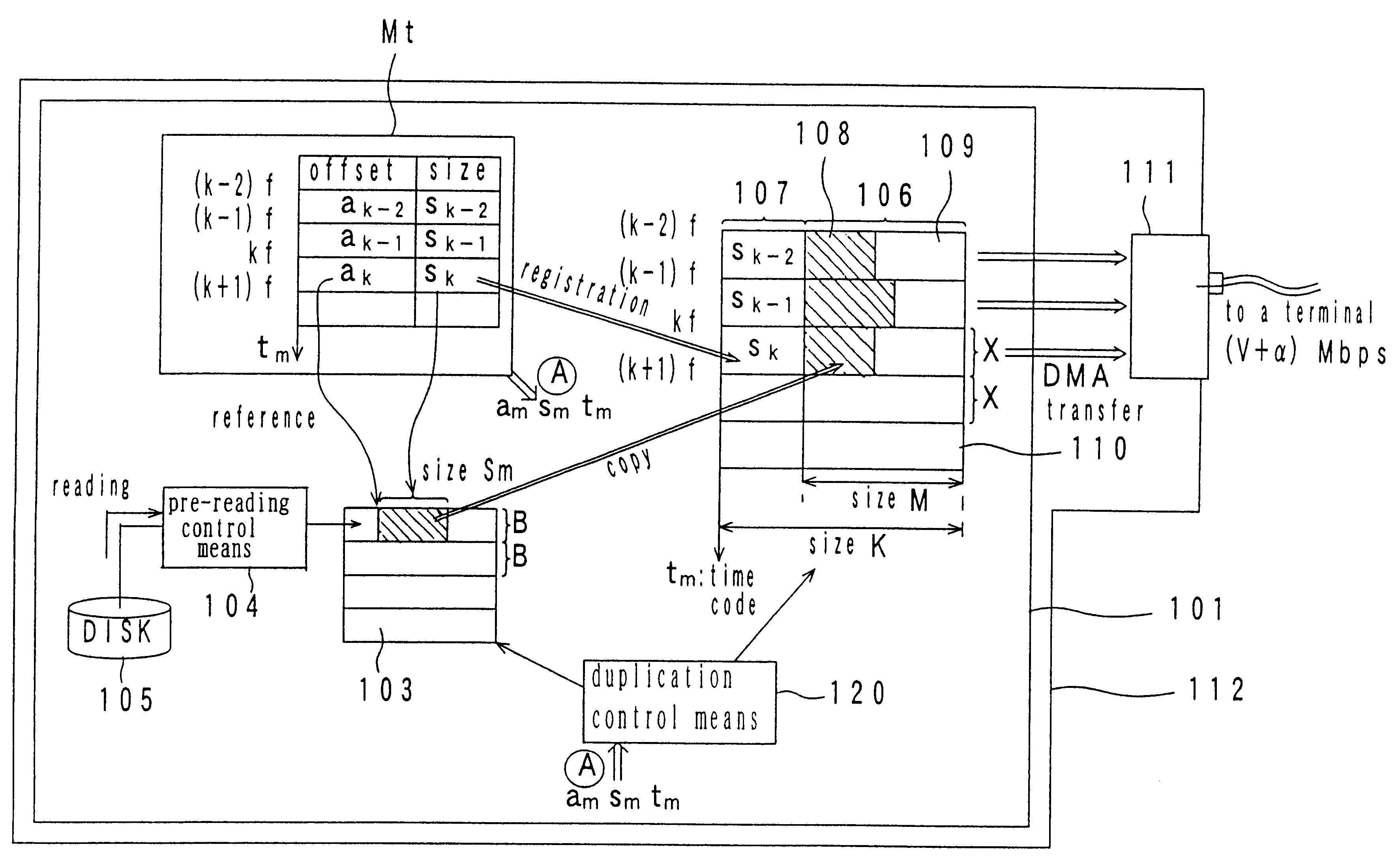
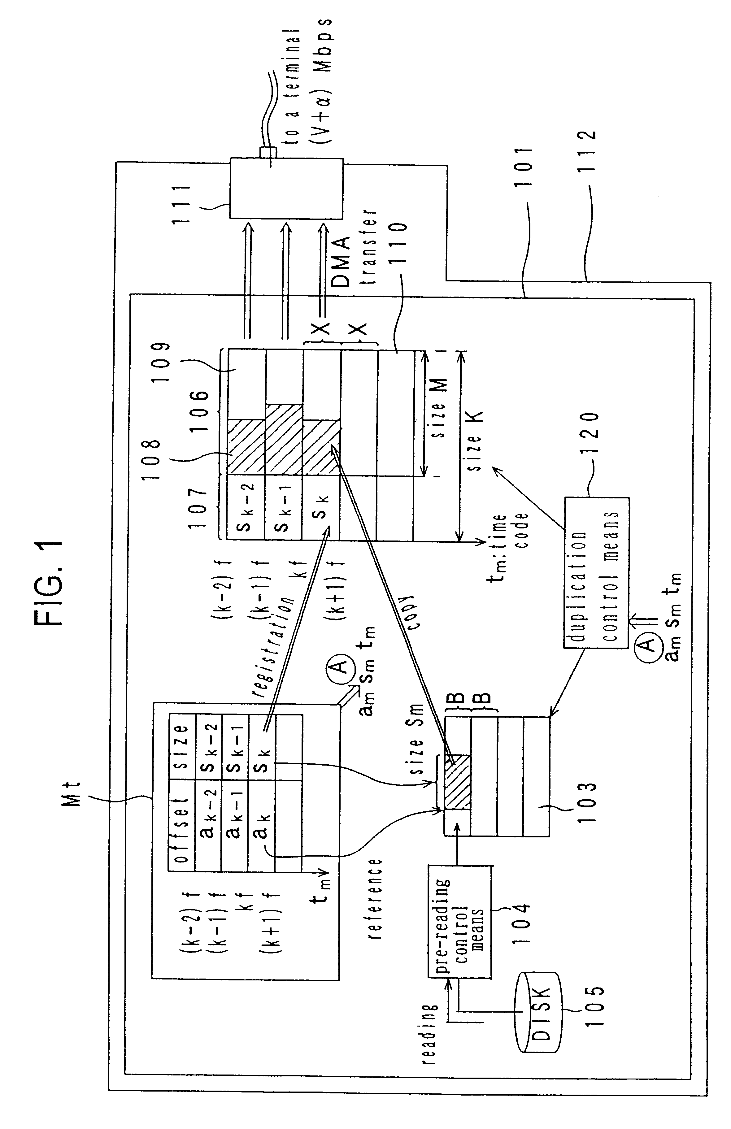
FIG. 1 is a functional block diagram of an example of the server system in which the present invention is applied, that is, an embodiment of the basic arrangement or configuration of the data stream output apparatus of the present invention.
In FIG. 1, a video server system 112 includes a data stream output apparatus 101 and a bus interface 111. This system sends out data real-time--multi-media data encoded in the MPEG program stream format--in the isochronous transfer method as a request for a data is received from the terminal or the server itself instructs the terminal that a data will be sent.
The isochronous transfer technique is a system of setting up a theoretical transfer channel with a fixed rate of data transmission (data size / time) between the sender and the receiver and of transferring data in the push-type manner (that is, data are sent out as they are ready at the sender without waiting to be so instructed by the receiver). In this technique, the transmission rate is con...
embodiment 2
FIG. 4 shows a system example in which a function to generate a time search map is incorporated in the data stream output apparatus shown in Embodiment 1.
As source data or uncoded data such as images and sounds is supplied to the data stream output apparatus 101 from outside, the source data is led to the MPEG encoder 402 and encoded by an encode engine 404 provided in the encoder 402. The MPEG encoder 402 is furthermore equipped with a system encoder 403. This system encoder 403 generates a system clock reference corresponding to the time code t.sub.m. The system clock reference is then registered on a pack header in a pack for multiplexing video and audio data generated by the encode engine 404 as mentioned.
In this connection, it is understood that the'synchronization between the video data and audio date is ensured by the system encoder 403. The encoded data is to be written in the disk unit 105 through the pre-reading control means 104. Here, the pre-reading control means 104 ha...
embodiment 3
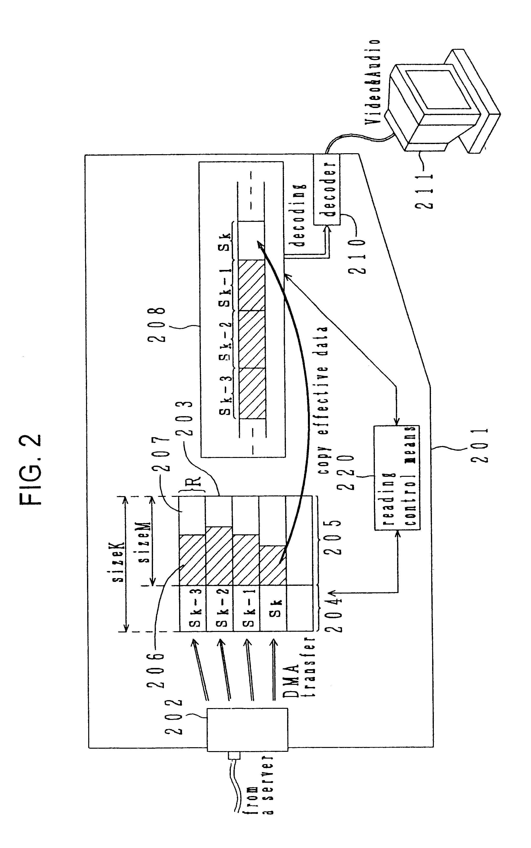
The preceding embodiment shows a configuration in which source data is inputted uncoded in the data stream output apparatus. FIG. 5 shows an arrangement where data already encoded in the MPEG format are inputted in the data stream output apparatus.
As data encoded in the MPEG format are supplied to the data stream output apparatus 101 from outside, those data are written in the disk unit 105 through the pre-reading control means 104 and led to the decoder 502 for data analysis. There, the pre-reading control means 104 performs a function to manage the data written in the disk unit 105.
Unless data are read out on the decoder 502 while the data are written in the disk unit 105, there is no need to synchronize the writing in the disk unit 105 with data analysis. Therefore, the MPEG decoder 502 has a decoder buffer 504 to input data temporarily depending on the analysis rate.
If data contained in a video pack indicate that the pack is forefront pack in one GOP, the MPEG decoding means 503...
PUM
| Property | Measurement | Unit |
|---|---|---|
| time | aaaaa | aaaaa |
| time | aaaaa | aaaaa |
| size | aaaaa | aaaaa |
Abstract
Description
Claims
Application Information
 - R&D
- Intellectual Property
- Life Sciences
- Materials
- Tech Scout
- Unparalleled Data Quality
- Higher Quality Content
- 60% Fewer Hallucinations
Browse by: Latest US Patents, China's latest patents, Technical Efficacy Thesaurus, Application Domain, Technology Topic, Popular Technical Reports.
© 2025 PatSnap. All rights reserved.Legal|Privacy policy|Modern Slavery Act Transparency Statement|Sitemap|About US| Contact US: help@patsnap.com


