
Hanger bracket for installing and supporting suspended equipment

Inactive Publication Date: 2002-10-01
NORTHWEST REFRIGERATION CONTRACTORS
View PDF17 Cites 48 Cited by
  • Summary
  • Abstract
  • Description
  • Claims
  • Application Information

AI Technical Summary

Benefits of technology

The present invention provides a hanger bracket that provides an intrinsically safe means for hanging heavy equipment from a ceiling or roof structure. The hanger bracket of the present invention utilizes the weight of the suspended equipment element to supplement the holding force of the hanger bracket.
Additionally, the hanger bracket of the of the present invention reduces the difficulties and risks associated with the installation of elevated or overhead equipment. The structural features of the hanger bracket of the present invention provides for the performance of several installation operation steps at the floor level. In the preferred method of the present invention, the hanger bracket is attached to the equipment element while the equipment is at floor level. The equipment element is then lifted to the final position with a minimum of further installation related operations performed at a high elevation off the floor.

Problems solved by technology

The overhead suspension of heavy equipment presents problems both in the installation of such equipment and in the continued safe support of the suspended equipment.
If the equipment load, borne by the L-shaped bracket, is heavy enough to overcome the gripping power of the U-bolts, the L-shaped bracket can slip off of the rod, and the equipment will fall.
Work performed well above the floor, up against the roof structure, requires a high level of safety-related precaution and so is performed slowly and at some risk.

Method used


Image

  • Hanger bracket for installing and supporting suspended equipment
  • Hanger bracket for installing and supporting suspended equipment
  • Hanger bracket for installing and supporting suspended equipment

Examples


Embodiment Construction

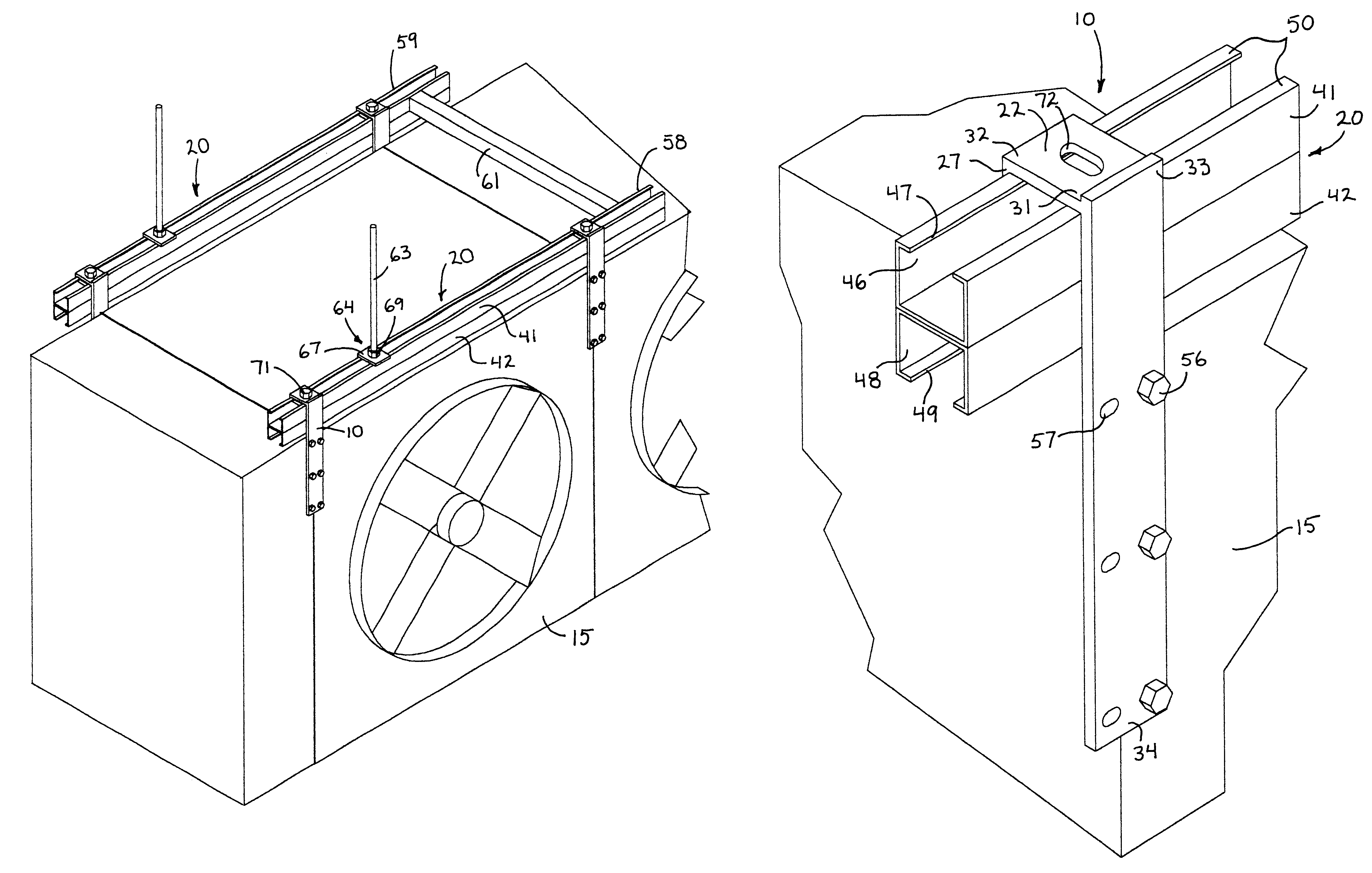
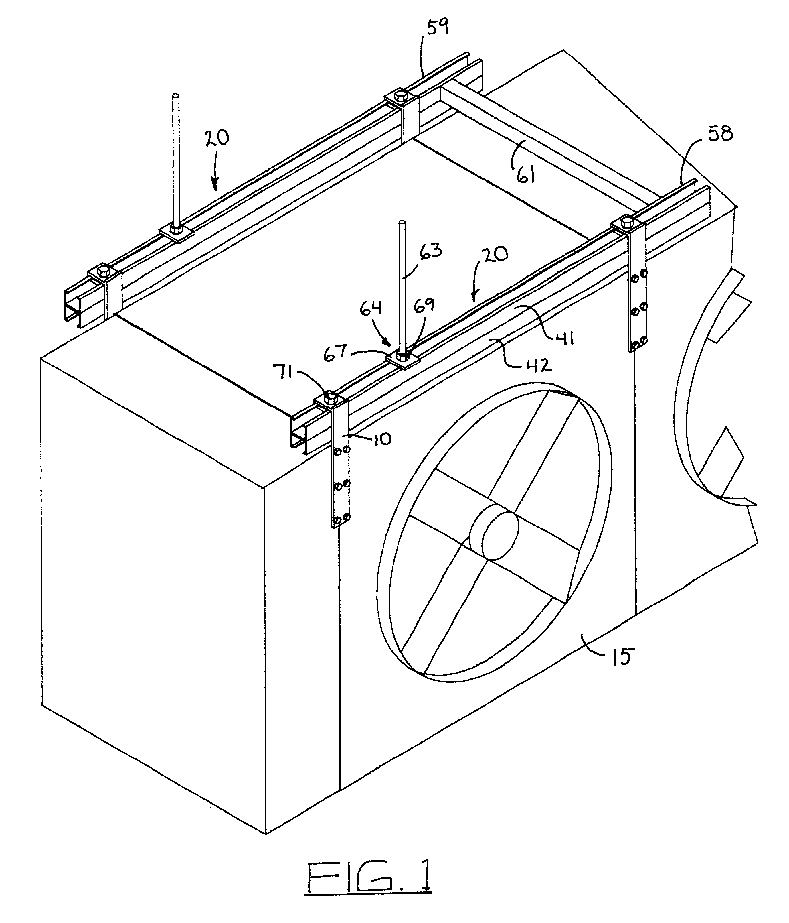
The invention provides hanger bracket and a method for installing and supporting suspended equipment with the hanger bracket. The hanger bracket 10 is shown in FIGS. 1 through 7, 9 and 10. FIG. 1 shows an equipment element 15 suspended from a support rail 20, which typifies an installation employing the hanger bracket of the present invention.

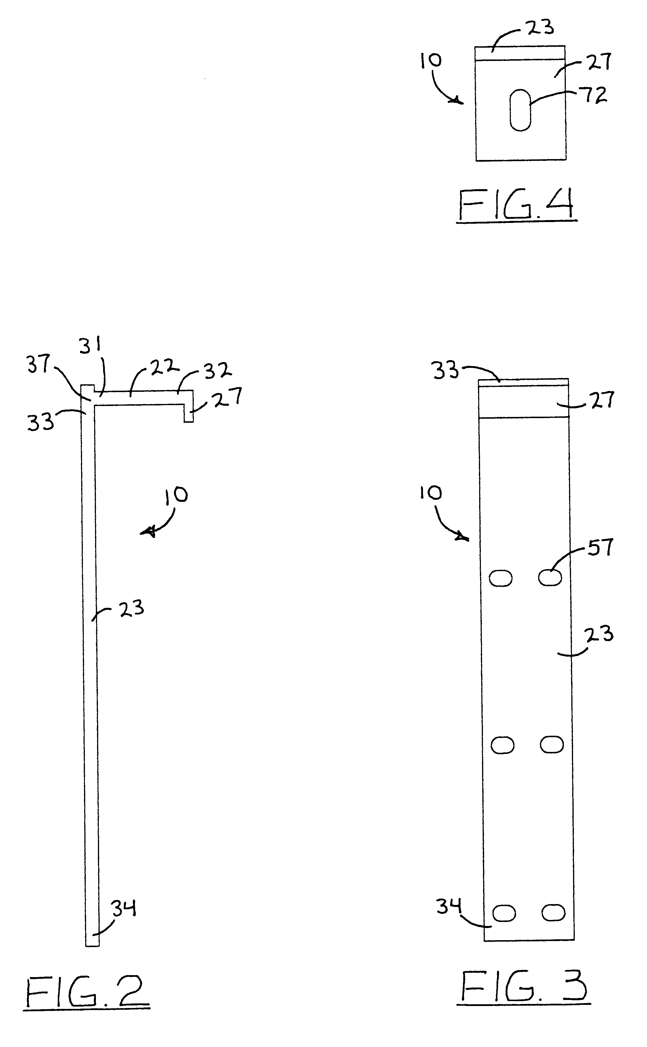
As detailed in FIGS. 2 and 5, the hanger bracket 10 the hanger bracket includes a rail cap 22 adjoined to a side bar 23. The rail cap and the side bar adjoin to the rail cap, approximately at a right angle to form a substantially inverted "L" shape.

As further detailed in FIG. 6, to achieve a secure mounting to the equipment element 15, the hanger bracket 10 is preferably installed with the sidebar 23 in a substantially vertical position, with the rail cap 22 at the top of the hanger bracket. The rail cap of the hanger bracket rests on the top of a support rail 20. The rail cap can also include a lip 27. The lip is shown in FIGS. 7 and 9 as exte...


PUM


Abstract

A hanger bracket for supporting suspended equipment from a support rail. The hanger bracket includes a rail cap adjoined to a side bar. The rail cap also includes a lip parallel to the sidebar. The rail cap rests on the top surface of the support rail. The lip adjoins to the rail cap at an opposite end of the rail cap from the sidebar. The hanger bracket, with the sidebar, the rail cap and the lip, has an inverted "J" shape. The sidebar of the hanger bracket mounts onto an element of the suspended equipment, so that the rail cap rests on a top surface of the support rail. A plurality of hanger brackets can support the equipment element on the support rail. The hanger bracket is first mounted to the equipment element of the overhead equipment, which is then lifted to raise the rail cap above a support rail. The equipment element is then shifted, to position the rail cap over the support rail. The equipment element is finally lowered to contact the rail cap with the top surface of the support rail. The hanger bracket can slide along the support rail to reposition the equipment element. The hanger bracket is intrinsically safe for hanging heavy equipment from a ceiling or roof structure as it utilizes the weight of the suspended equipment element to supplement the holding force of the hanger bracket, allowing the performance of several installation steps at the floor level.

Description

The invention relates to a method and apparatus for a hanger bracket, and more particularly to a method for installing and supporting suspended equipment with the hanger bracket.The overhead suspension of heavy equipment presents problems both in the installation of such equipment and in the continued safe support of the suspended equipment. Heavy equipment is often suspended from the underside of roofs or similar overhead structures in buildings or facilities, such as warehouses, auditoriums, garages and aircraft hangers. The function of this overhead equipment may be for such purposes as exhaust, ventilation, heating, cooling, electrical, or lighting, to name a few.The installation of heavy overhead equipment is conventionally performed with the aid of hydraulic lifts or cranes that hoist the equipment to its installed location at the required height above the floor surface. Skilled construction technicians employ conventional hangers, bolts or straps to connect elements of the eq...

Claims


Application Information

Patent Timeline
IPC IPC(8): E04B9/00F24F13/32
CPCE04B9/006F24F13/32
Inventor GOHL, JR., WAYNE F.
Owner NORTHWEST REFRIGERATION CONTRACTORS
Learn More