Eureka AIR delivers breakthrough ideas for toughest innovation challenges, trusted by R&D personnel around the world.

Photocontroller diagnostic system

a technology of diagnostic system and photocontroller, which is applied in the direction of lighting apparatus, electrical equipment, light sources, etc., can solve the problems of severe problems such as safety hazards, wasting electricity, and servicing faulty photocontrollers, and achieve the effects of reducing rfi, saving electricity, and preventing premature failure of ballasts and starters

Inactive Publication Date: 2002-09-17
ABL IP HLDG
View PDF17 Cites 88 Cited by
  • Summary
  • Abstract
  • Description
  • Claims
  • Application Information

AI Technical Summary

Benefits of technology

It is a further object of this invention to provide such a system and method which, because of its ability to detect cycling, saves electricity, reduces RFI, and prevents the premature failure of ballasts and starters associated with luminaries.
It is a further object of this invention to provide such a system and method which significantly reduces the cost of servicing and repairing luminaries such as street lights.
It is a further object of this invention to provide such a system and method which can be implemented in a cost effective way without the need for making complicated modifications to existing luminaries and / or the use of expensive fiber optic sensors.
This invention results from the further realization that cycling of a street light and other faulty luminaire conditions such as a lamp out condition can be detected by monitoring the load drawn by the lamp at different times and then comparing the load differences to pre-determined thresholds, that such detection can be accomplished by an inexpensive transformer added to the photocontroller circuitry and coupled to a specially programmed microprocessor, and that a transmitter can be linked to the microprocessor to transmit lamp out, lamp cycling, and other fault conditions to a location remote from the street lamp to initiate repair / maintenance services in real time. Alternatively, the microprocessor can illuminate one or a series of LEDs resident on the photocontroller to provide repair personnel with a positive indication regarding the condition of the photocontroller and / or lamp even in the daylight hours when the lamp is purposefully turned off. Further, the controller can shut the lamp off after a predetermined number of cycles. This feature eliminates ballast and starter degradation.

Problems solved by technology

Since the cost of servicing a single street light can cost $100 or more on busy roads and in busy areas, and since there are 60,000,000 street lights in the United States alone, the problem of servicing faulty photocontrollers is severe.
For example, when the relay of the photocontroller fails, or when the photocell fails, the street light will remain on during periods of daylight thereby wasting electricity.
Alternatively, a faulty relay or a faulty photocell could cause the lamp to remain off during the night causing a safety hazard.
Since repair typically occurs during daylight hours, it is often difficult to detect the latter condition.
The problem of high pressure sodium (HPS) street lights cycling at the end of their useful life is also severe.
The result is "cycling" wherein the worn out lamp keeps trying to stay lighted.
Cycling may waste electricity, cause RFI (radio frequency interference) which adversely effects communication circuits, radios, and televisions in the area, and may adversely effect and prematurely wear out the ballast, starter, and photocontroller.
For example, if an HPS lamp undergoes cycling for a many nights before it is finally serviced and replaced, the ballast or starter can be damaged or degraded.
But, when the HPS lamp is replaced, this damage or degradation might not be detected.
The ballast and starter components are more expensive than the lamp or the photocontroller.
Unfortunately, this prior art solution requires modifications to the existing light fixture (e.g. a hole must be drilled in the fixture housing) and the use of an expensive fiber optic sensor.
Another problem with all luminaries including HPS or other types of lamps is the cost involved in correcting the cycling problem and other faults such as a lamp out condition.
Considering the fact that the lamp pole may be 25-35 ft. high, repair personnel can waste a considerable amount of time checking each lamp in the area.
Also, repair and maintenance personnel may not be able to service a given residential area until daylight hours when all of the street lights are off by design.

Method used


Image

  • Photocontroller diagnostic system
  • Photocontroller diagnostic system
  • Photocontroller diagnostic system

Examples


Embodiment Construction

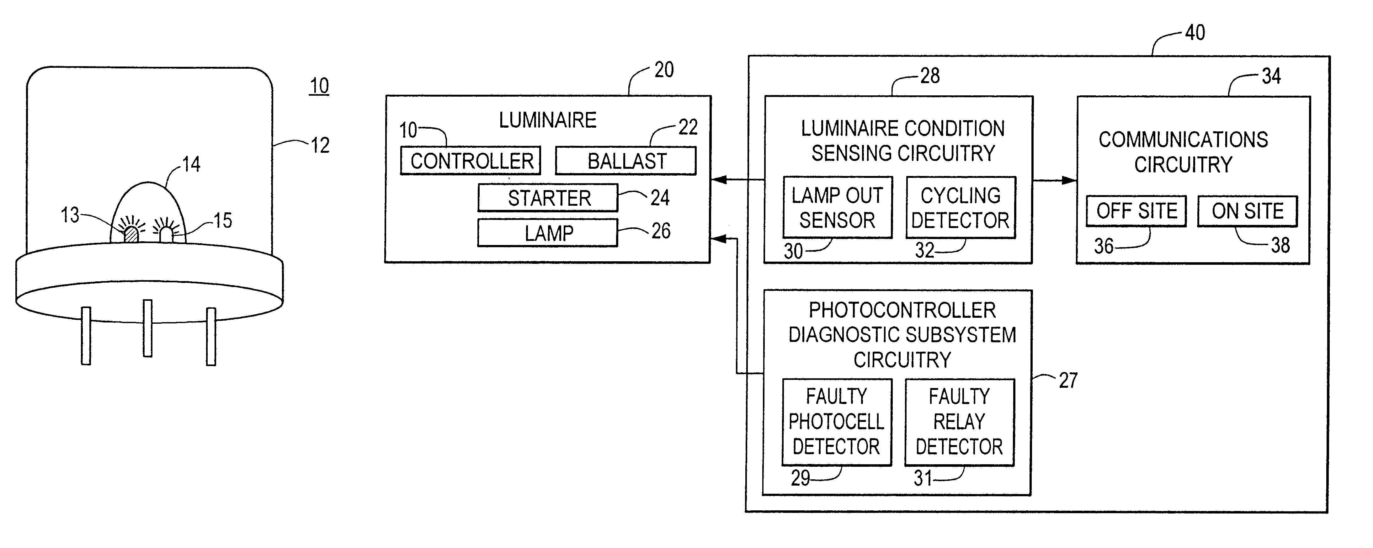
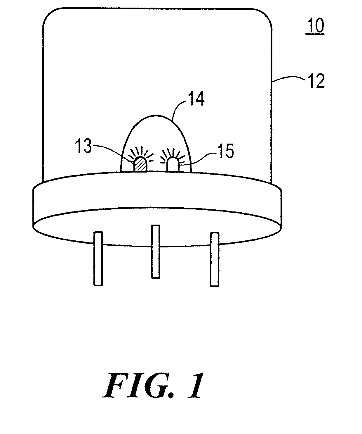
Photocontrol device 10, FIG. 1, includes thermoplastic, high impact resistant, ultraviolet stabilized polypropylene cover 12 and clear window 14 made from UV stabilized, UV absorbing, acrylic for the light sensor which resides on a circuit board within cover 12. Photocontrol device 10 is typically configured to fit an ANSI C136.10 receptacle but may be mounted in an ANSI C136.24 "button" package or other enclosure. Photocontroller 10 is typically mounted on a street light at the top of a light pole. Photocontroller 10 may also be used, however, in conjunction with other types of luminaries and other devices such as golf course water fountains.

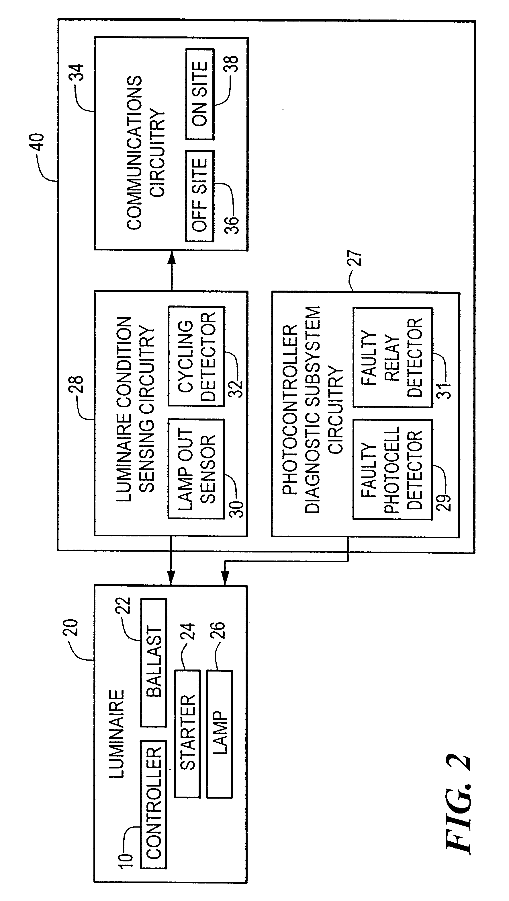
The circuit board within cover 12 is configured to operate in accordance with the block diagram shown in FIG. 2 and the specific circuit diagram shown in FIG. 3. Microcontroller 54 shown in the circuit diagram of FIG. 3 is programmed in accordance with the flow charts shown in FIGS. 4, 5, and 6 in accordance with this invention, and transmitter...


PUM


Abstract

A photocontroller diagnostic system including a photocontroller with a sensor for determining the presence of daylight, and a relay, responsive to the sensor, for de-energizing a lamp during periods of daylight. The diagnostic subsystem is responsive to the photocontroller, and includes a microprocessor programmed to verify the operability of the relay and / or the sensor and programmed to transmit a signal representative of the operability of the relay or the sensor.

Description

This invention relates to a photocontroller diagnostic system which, inter alia, detects whether the photocell and the relay of the photocontroller are faulty and which also provides an indication of a faulty relay or photocell condition by transmitting information about that condition to a remote base station and / or illuminating a signal light on the photocontroller.Photocontrollers are typically mounted on street lights and operate to turn the light off during the day and on at night. Since the cost of servicing a single street light can cost $100 or more on busy roads and in busy areas, and since there are 60,000,000 street lights in the United States alone, the problem of servicing faulty photocontrollers is severe. For example, when the relay of the photocontroller fails, or when the photocell fails, the street light will remain on during periods of daylight thereby wasting electricity. Alternatively, a faulty relay or a faulty photocell could cause the lamp to remain off durin...

Claims


Application Information

Patent Timeline
Patent Type & Authority Patents(United States)
IPC IPC(8): H05B37/03H05B37/00
CPCH05B37/03H05B47/20
Inventor MORRISSEY, JOSEPH F.WALTERS, JEFF
Owner ABL IP HLDG
Why Eureka
Eureka Blog
Learn More