
Pipe testing apparatus

a testing apparatus and pipe technology, applied in the direction of instruments, structural/machine measurement, construction, etc., can solve the problems of loss of oil and gas, environmental pollution, injuring personnel at the well site, and affecting the safety of the pipe, so as to achieve the effect of adjusting the length of the tool and the distance between the upper and lower packers

Inactive Publication Date: 2002-08-13
TRAHAN P WARREN +2
View PDF19 Cites 29 Cited by
  • Summary
  • Abstract
  • Description
  • Claims
  • Application Information

AI Technical Summary

Benefits of technology

A novel feature of applicant's present invention is that the upper and lower packers can be set and released independent of each other. In the preferred embodiment the lower packer is set with a piston driven by fluid pressure created in a pressurized fluid line, water being the preferred pressurized fluid, and the upper packer is set with a piston driven by gas pressure created in a pressurized gas line comprised of the testing gas.
The length of the tool and the distance between the upper and lower packers can be altered by the addition of "subs", i.e. threaded sections of tool sized pipe, to adapt the tool to test connection assemblies of different lengths. Changes in tool length will allow the tool to test connections of downhole tool assemblies that are often linked together on the pipe string. Consequently, it is an object of applicant's present invention to provide a pressure testing device with upper and lower packers that will allow the upper and lower packers to be set and released independent of each other.
It is another object of applicant's invention to provide a pressure testing device that will allow the tool to be extended in length as may be required.
It is still another object of applicant's invention to provide a pressure testing tool with upper and lower packers that will allow the lower packer to be set in the pipe string independent of the upper packer so as to allow evacuation of drilling mud from the pipe string in the area above the lower packer.
It is another object of applicant's invention to provide a pressure testing tools that will reduce the incidence of "tool kick" during use.

Problems solved by technology

Oil or gas escaping from the pipe string into the annulus between the casing and the pipe string due can create a dangerous situation that may create an explosion, loss of the well, or both, and cause the loss of the oil and gas, environmental pollution, and injures to the personnel at the well site.
A potential point of leakage or threat to the pressure integrity of the pipe strings is at the connection point, i.e., the threaded connection, between the pipe segments that make making up the pipe strings.
A problem associated with the aforementioned tools and testing methods is the risk of a "tool kick" or rapid displaced of the tool caused when the high pressure testing gas in the testing chamber is released downward into the pipe string.
The rapid release of pressurized gas down the pipe string may displace the tool upwardly with tremendous force creating a risk of injury to the personnel performing the pressure test and damage to the testing assembly, all increasing the costs and risks of the pressure testing.
Another problem associated with the present testing tools and methods may arise during the testing of connections of long pipe strings running into the well bore.
The drilling fluids can cause the testing tool to float above the fluid making the correct or desired placement of the tool difficult.
The drilling fluid may then restrict the flow of testing gas or block the leak path of the testing gas causing the connection to appear to be leak free.
When the drilling fluid is removed from the pipe string during production, the undetected leak can cause problems with the well.

Method used


Image

  • Pipe testing apparatus
  • Pipe testing apparatus
  • Pipe testing apparatus

Examples


Embodiment Construction

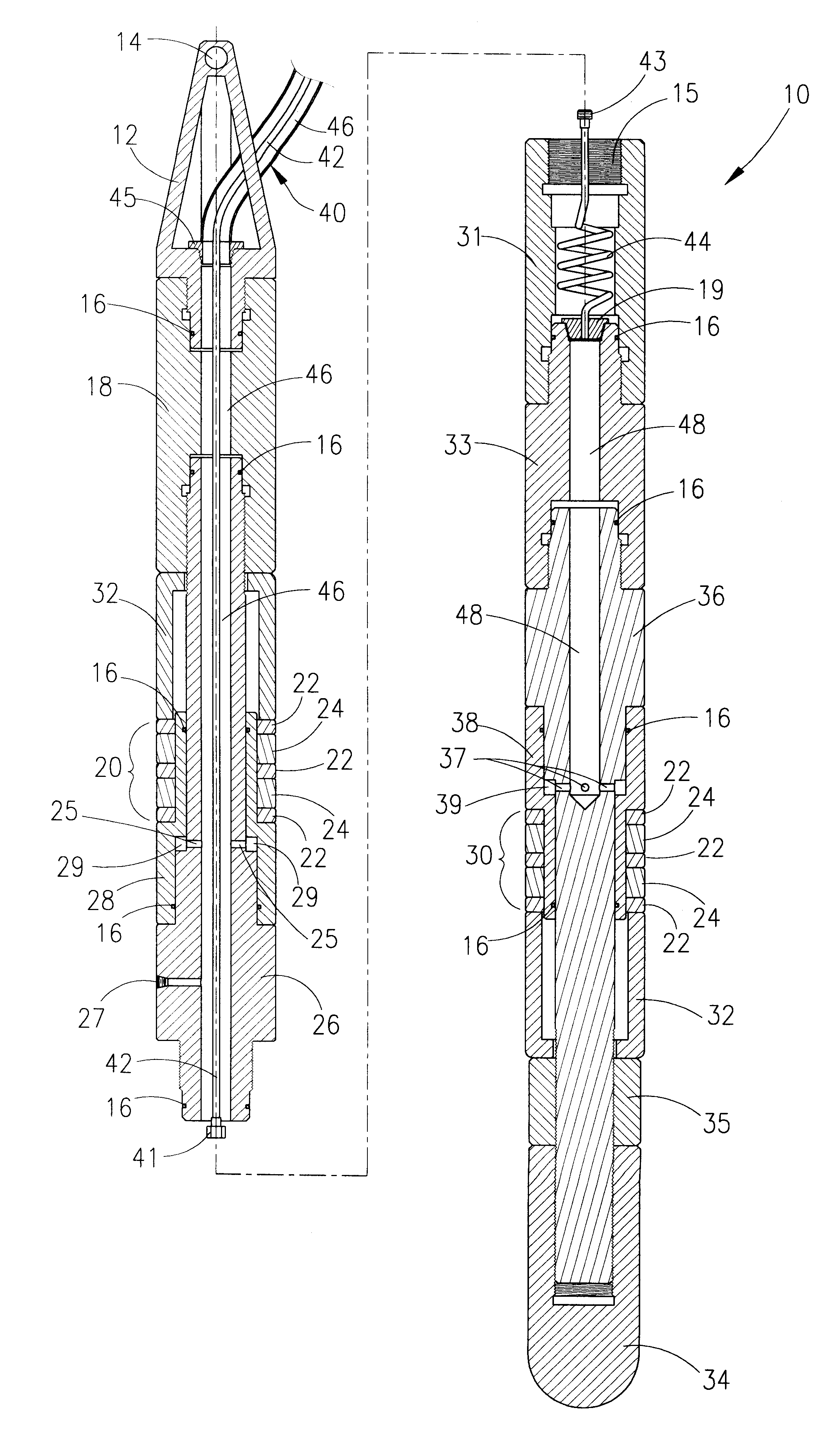
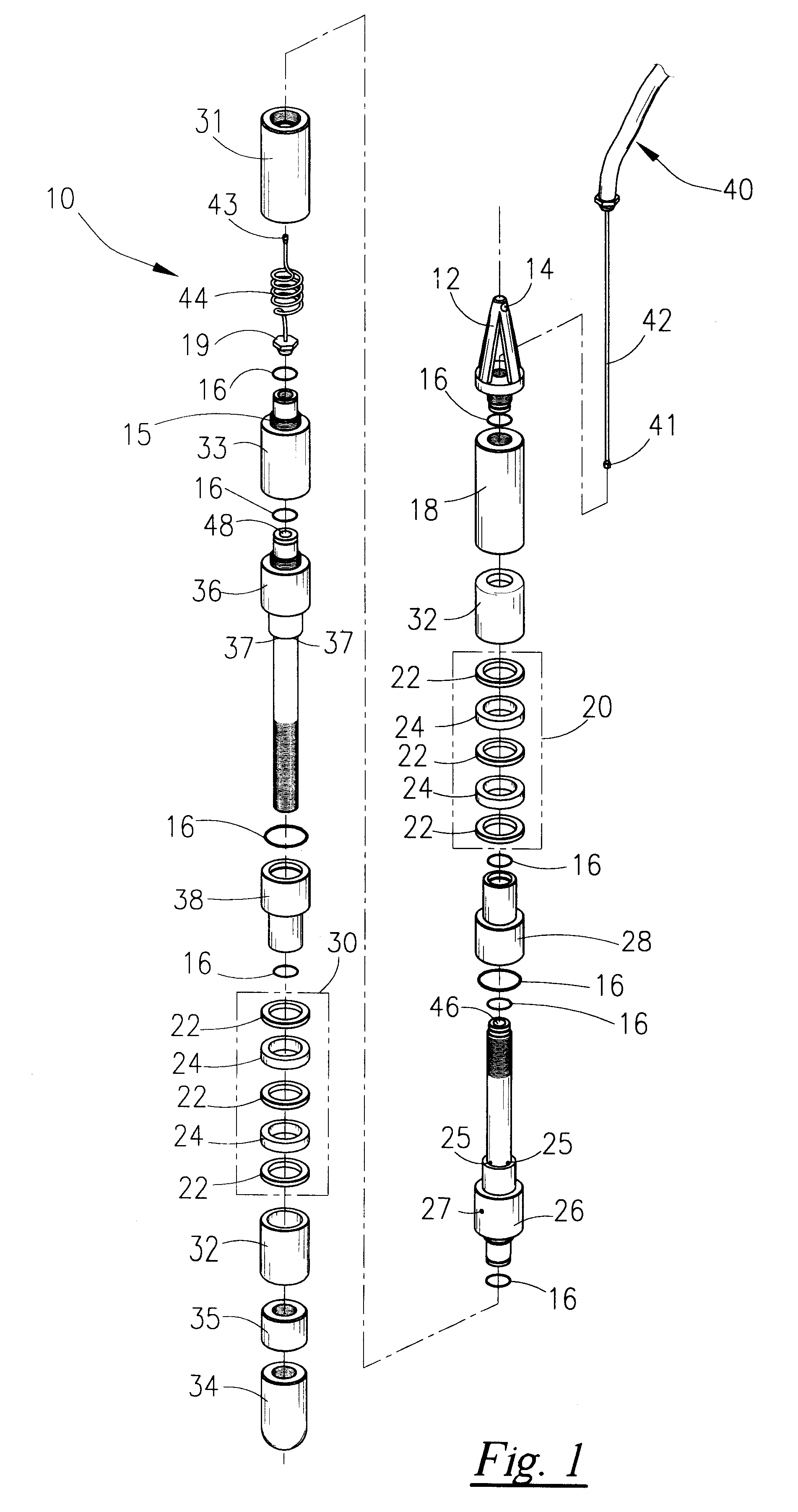
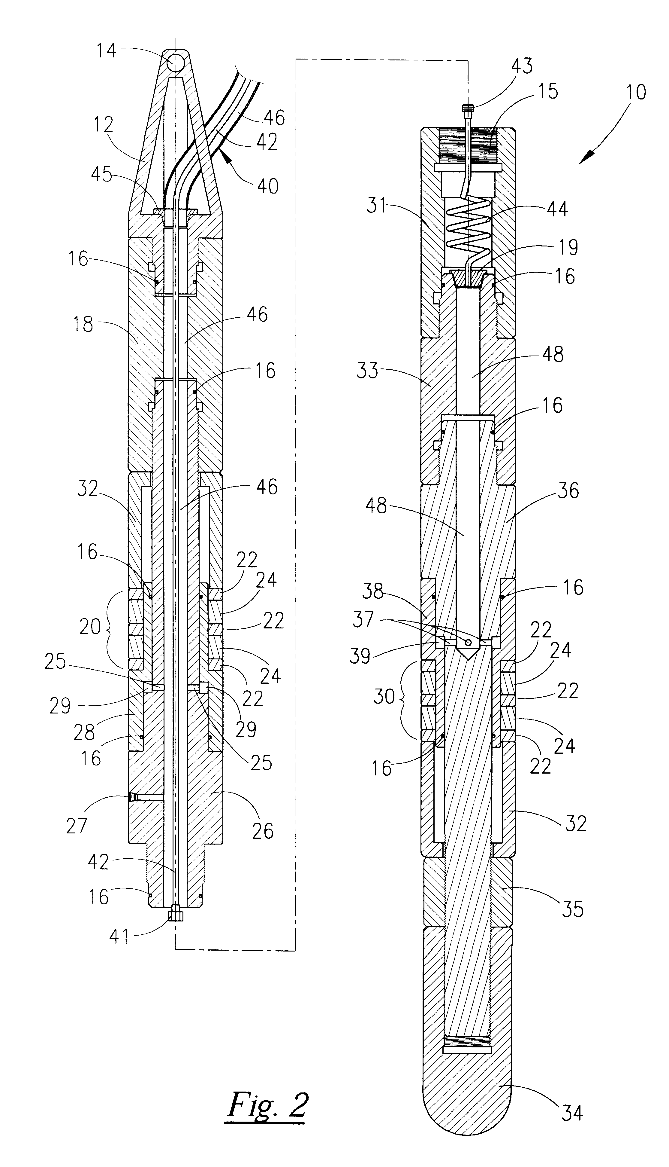
Referring now to the drawings and more particularly to FIG. 1 there is shown an exploded view of the preferred embodiment of the generally cylindrical pressure testing tool (10) of applicant's present invention. The testing tool (10) is comprised on a series of generally cylindrical tubular sections fitted together by means of a plurality of threaded connections (15), male and female, each connection sealed by O-rings (16). The tool (10) has an upper packer seal assembly (20) and a lower packer seal assembly (30) spaced a desired distance apart for sealably holding the tool within a desired portion of a pipe string. The tool (10) has a lifting sub (12) having a lifting eye (14). The lifting sub (12) allows the tool (10) to be raised, lowered and positioned on the pipe string with a hoist, not shown, on a rig floor. Connected to the tool (10) is a gas hose assembly (40) through which runs a fluid line (42).

As shown in FIG. 2 and FIG. 3, the gas hose assembly (40) is connected to the ...


PUM


Abstract

An apparatus for forming a test chamber within a tubular and internally pressure testing the tubular with a test gas. The apparatus is comprised of a generally cylindrical tester body having first and second spaced-apart sealing assemblies that are expandable against the inner wall of the tubular by a piston assembly so as to form a test chamber defined by the inner wall of the tubular and the expanded seal assemblies. The pistons of the first sealing assembly are gas actuated pistons acting in cooperation with the seals of the first sealing assembly in response to a gas under pressure. The pistons of the second sealing assembly are fluid actuated pistons acting in cooperation with the seals of the second sealing assembly in response to a fluid under pressure. The pressure of the gas and the pressure of the fluid used to actuate the first and second pistons are controlled independently of each other. The gas used to activate the first set of pistons is directed to the test chamber to serve as a test gas. The apparatus includes a sleeve container for retaining gas escaping from the test chamber to the exterior of the tubular. The sleeve container is provided with a gas detector for detecting the presence of test gas in the sleeve and a signal transmitter for generating signals indicating the presence of absence of test gas in the sleeve container. The preferred pressurized gas is helium and the preferred pressurized fluid is water.

Description

The present invention generally relates to the field of drilling oil and gas wells and, more particularly, relates to an apparatus for testing the integrity of pipe segments, especially the connections between joints of pipe.BACKGROUND OF INVENTIONIn the oil and gas industry, many sections or lengths of tubular pipe are commonly strung together to form pipe strings or tubing strings often measuring many of thousands of feet in length. These pipe strings are employed in oil and gas wells to convey oil and natural gas from their subsurface environments to the surface of the wells. Typically, the pipe string is inserted within a string of larger diameter pipe known as casing. The pipe casing is intended to support and seal the walls of the well bore hole.Because the oil and gas in the pipe string is typically conveyed to the surface of the wells at high pressures, the pressure integrity of the pipe string must be maintained. Oil or gas escaping from the pipe string into the annulus bet...

Claims


Application Information

Patent Timeline
Patent Type & Authority Patents(United States)
IPC IPC(8): G01M3/22G01M3/20
CPCE21B47/1025G01M3/223E21B47/117
Inventor MALLET, RONALD JAMES
Owner TRAHAN P WARREN
Learn More