
Water-saving device for a toilet having a sink with a float-operated drain valve

Inactive Publication Date: 2002-07-30
CHEN JUNG HUA
View PDF4 Cites 34 Cited by
  • Summary
  • Abstract
  • Description
  • Claims
  • Application Information

AI Technical Summary

Benefits of technology

wherein when the water in the chamber of the tank is lowered to a predetermined level after flushing, the valve is opened to allow the water in the inlet tube to enter the filling tube, a portion of the water from the filling tube entering the chamber of the tank via said at least one transverse hole, a remaining portion of the water from the filling tube entering the sink via the second end of the filling tube and the outlet tube, the plug being moved to a position preventing drainage of water in the sink via the hole.
wherein when the water in the chamber of the tank is lowered to a predetermined level after flushing, the valve is opened to allow the water in the inlet tube to enter the filling tube, a portion of the water from the filling tube entering the chamber of the tank via said at least one transverse hole, a remaining portion of the water from the filling tube entering the sink via the second end of the filling tube and the outlet tube, the plug is moved to a position plugging the hole in the sink and thus preventing drainage of water in the sink via the hole; and
wherein when the water handle is in a closed position and when the water in the chamber of the tank is lowered to a predetermined level after flushing, the valve is opened to allow the water in the inlet tube to enter the filling tube, a portion of the water from the filling tube entering the chamber of the tank via said at least one transverse hole, a remaining portion of the water from the filling tube entering the sink via the second end of the filling tube and the outlet tube, the plug is moved to a position plugging the hole in the sink and thus preventing drainage of water in the sink via the hole;

Problems solved by technology

However, no plug is provided for plugging the drainage hole such that the water from the spout is drained into the tank immediately.
The use of water is not so effective.
In addition, the sound of drainage of the water from the sink into the tank via the drainage hole is relatively loud, which would sound even louder when using the toilet in the night.

Method used


Image

  • Water-saving device for a toilet having a sink with a float-operated drain valve
  • Water-saving device for a toilet having a sink with a float-operated drain valve
  • Water-saving device for a toilet having a sink with a float-operated drain valve

Examples


Embodiment Construction

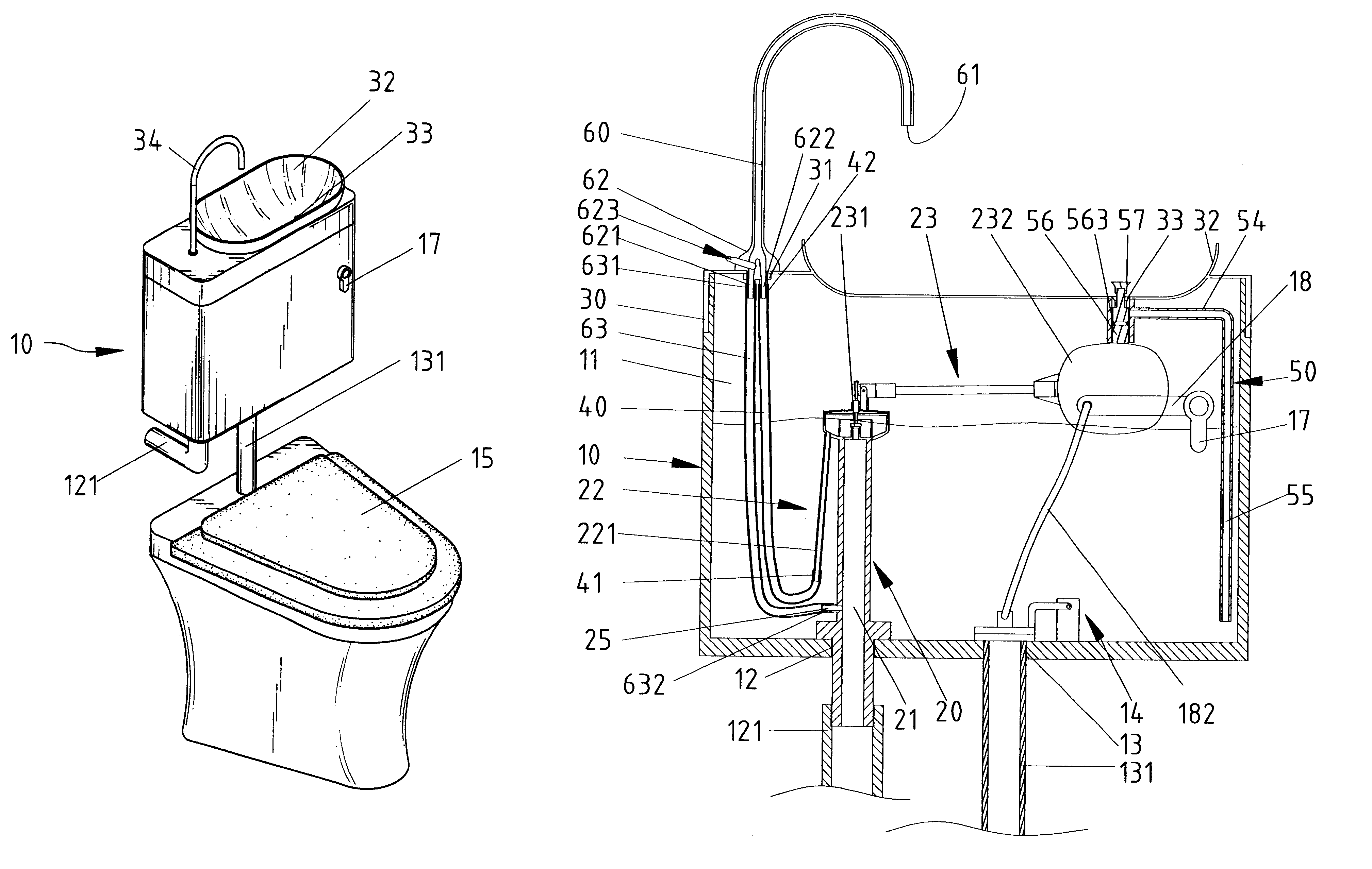
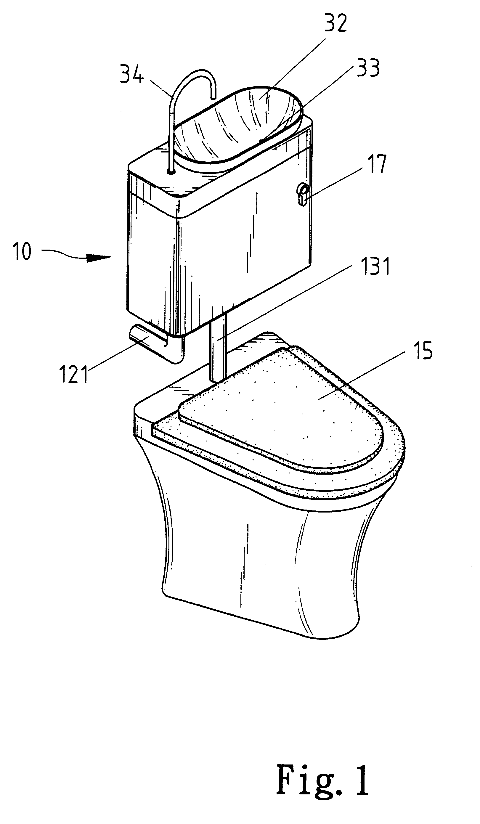
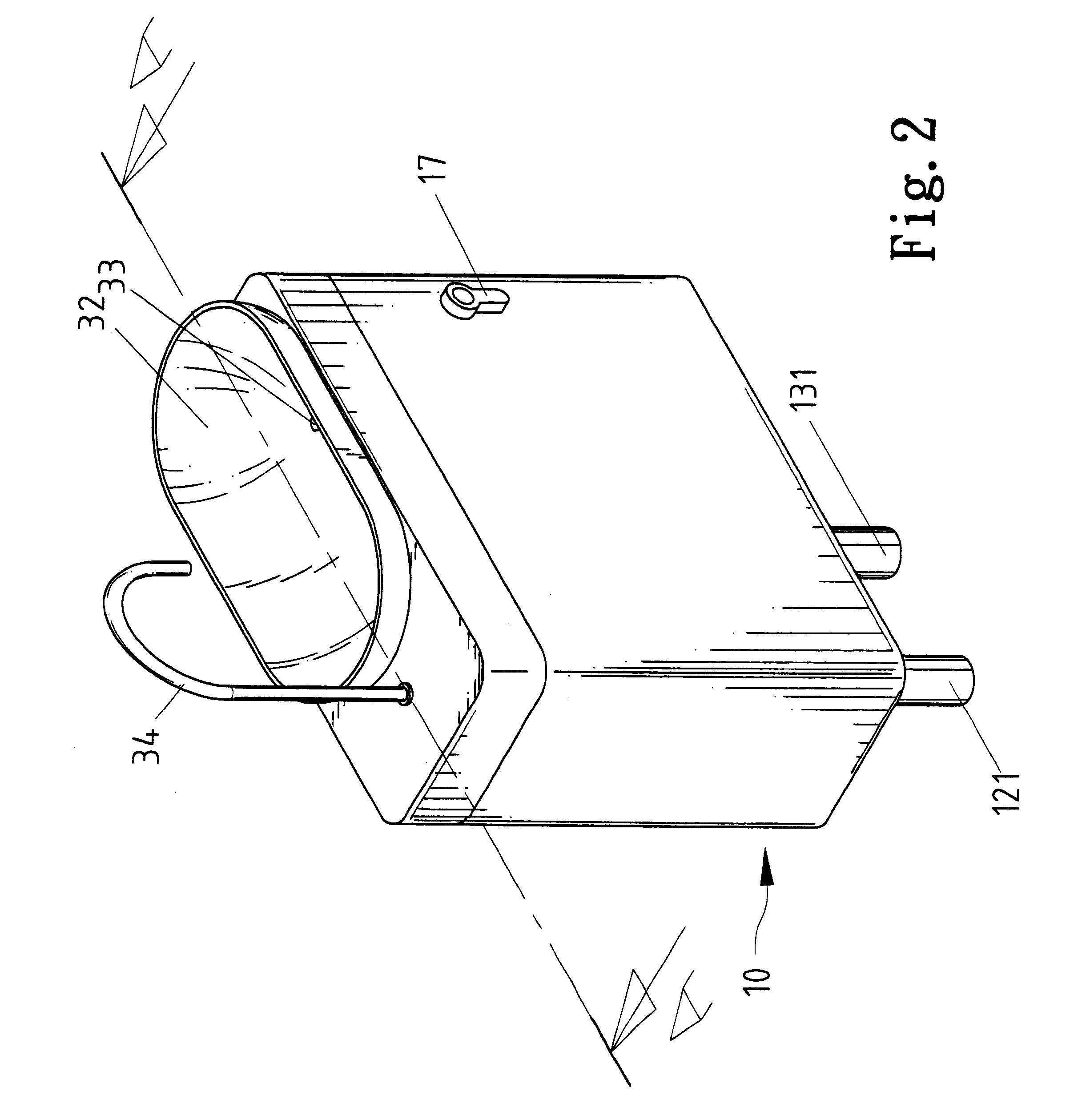
Referring to FIGS. 1 through 4, a water-saving device in accordance with the present invention generally comprises a tank 10 defining a chamber 11 for receiving water. Defined in a bottom wall defining the chamber 11 is an inlet 12 to which an inlet pipe 121 is connected and an outlet 13 (FIG. 4) to which an outlet tube 131 is connected. An outlet cover 14 is pivotally mounted to the bottom wall defining the chamber 11 for covering the outlet 13 and thus stopping drainage of water from the tank 10 into a bowl 15 (FIG. 1) located below the tank 10.

A flush handle 17 has a threaded stem 171 that extends through a hole 16 in a side of the tank 10 into the chamber 11 and through a hole 181 in an end of a link 18 and is then engaged with a nut 19, thereby pivotally mounting the flush handle 17 to the tank 10. The other end of the link 18 is connected to the outlet cover 14 via a lift wire 182 such that the outlet cover 14 is lifted upward when the flush handle 17 is pivoted, thereby drain...


PUM


Abstract

A water-saving device for a toilet comprises a tank, a tank lid mounted on top of the tank, a sink formed on the sink and communicated with a chamber in the tank via a hole in the sink, and an output tube having a lower end communicated with an inlet tube and an upper end for supplying water into the sink. A guide tube is mounted in the tank and comprises an upper end communicated with the hole of the sink and a lower end immersed in the water in the chamber of the tank such that drainage of water in the sink via the hole of the sink and the guide tube into the chamber of the tank is almost silent.

Description

1. Field of the InventionThe present invention relates to a water-saving device for a toilet.2. Description of the Related ArtA device has been proposed to save water when using a toilet. The device comprises a sink defined in the tank lid. An output tube has a lower end communicated with an inlet tube in the tank and an upper end with a spout for outputting water. Thus, the user may wash his or her hands in the sink with the water from the spout. A drainage hole is defined in a bottom of the sink for draining used water into the tank for flushing the toilet. However, no plug is provided for plugging the drainage hole such that the water from the spout is drained into the tank immediately. The use of water is not so effective. In addition, the sound of drainage of the water from the sink into the tank via the drainage hole is relatively loud, which would sound even louder when using the toilet in the night.An object of the present invention is to provide a water-saving device for a ...

Claims


Application Information

Patent Timeline
IPC IPC(8): E03D1/00
CPCE03D1/003
Inventor CHEN, JUNG-HUA
Owner CHEN JUNG HUA
Learn More