
Railway box car structure

a box car and railway technology, applied in the direction of railway bodies, transportation and packaging, window arrangements, etc., can solve the problems of cargo damage, particularly hazardous, requiring further handling and insurance claims, and achieve the effect of improving the longitudinal side wall structur

Inactive Publication Date: 2002-07-23
IEC HOLDEN INC
View PDF7 Cites 22 Cited by
  • Summary
  • Abstract
  • Description
  • Claims
  • Application Information

AI Technical Summary

Benefits of technology

It is therefore a feature of the present invention to provide a railway box car structure having an improved longitudinal side wall structure whereby the inner ferrous sheet cladding forms flush inner side walls free of any obstructions.
Another feature of the present invention is to provide an improved roof frame with stiffeners and capable of incorporating therein skylights of improved design.

Problems solved by technology

These welds or fasteners will cause damage to cargo if the cargo is thrust against the wall by sudden braking or acceleration of the railway car.
This is particularly hazardous when the lading is a fragile material such as paper rolls.
Such damaged rolls also require further handling and insurance claims and require more effort on the part of all concerns.
Accordingly, it can be seen that damage to such lading is troublesome and very costly.
This patent is not concerned with load shifting but particularly damage to products during the loading and unloading process when the product is manipulated inside the box car by forklift trucks during loading and unloading.
While passenger railway car bodies have been greatly improved in the past, very little design work has been directed to improving box car designs whereby to transport goods in a safer and more efficient manner.

Method used


Image

  • Railway box car structure
  • Railway box car structure
  • Railway box car structure

Examples


Embodiment Construction

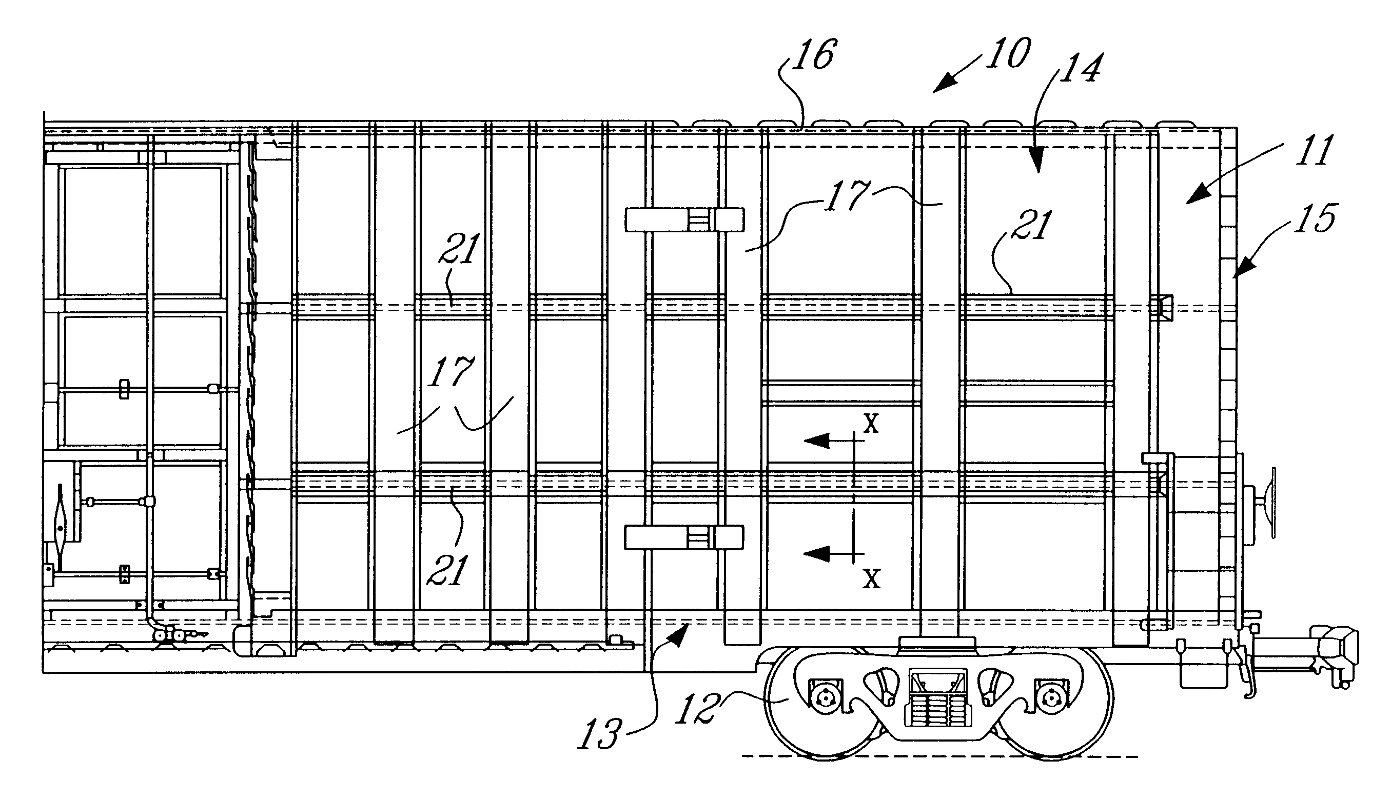
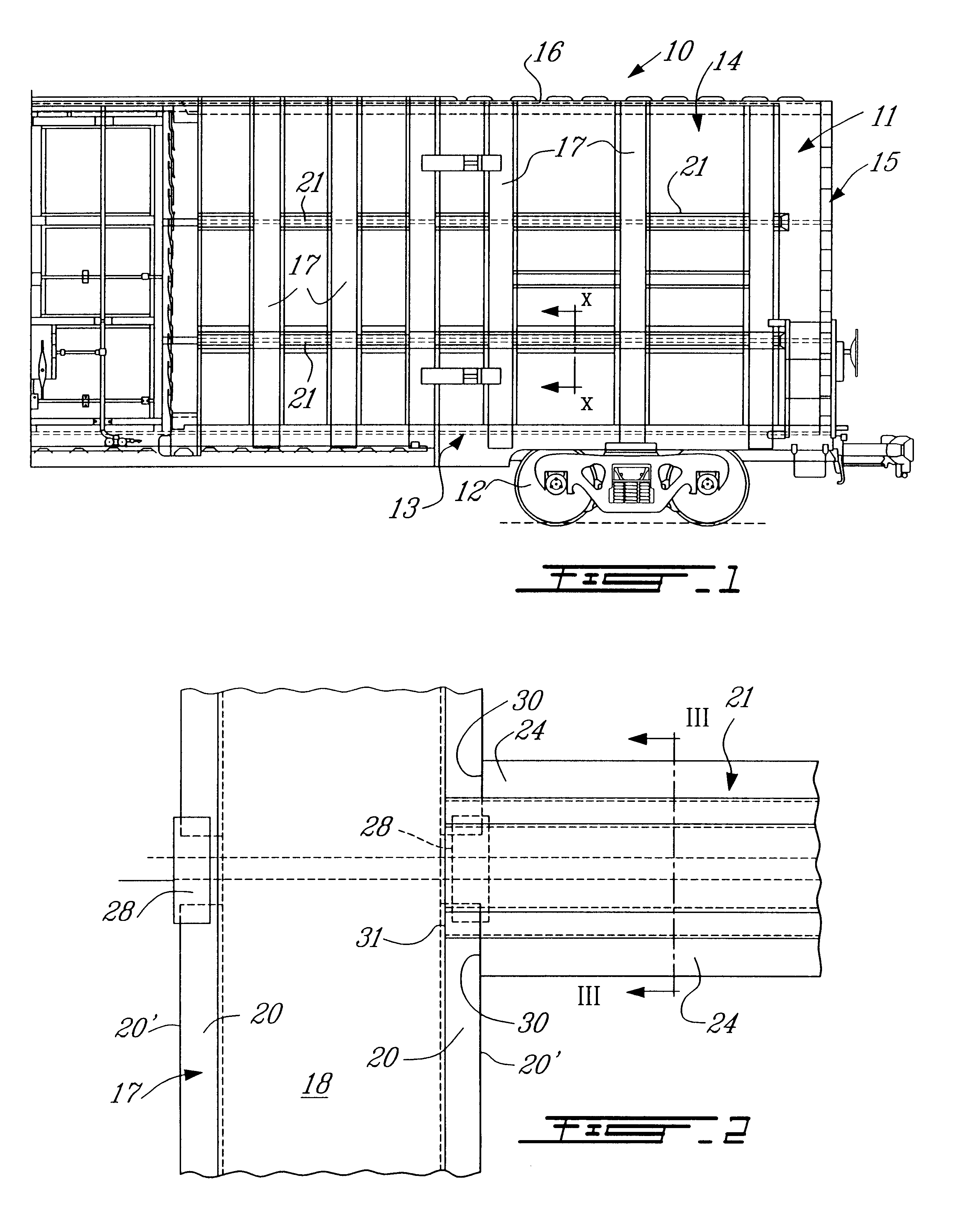
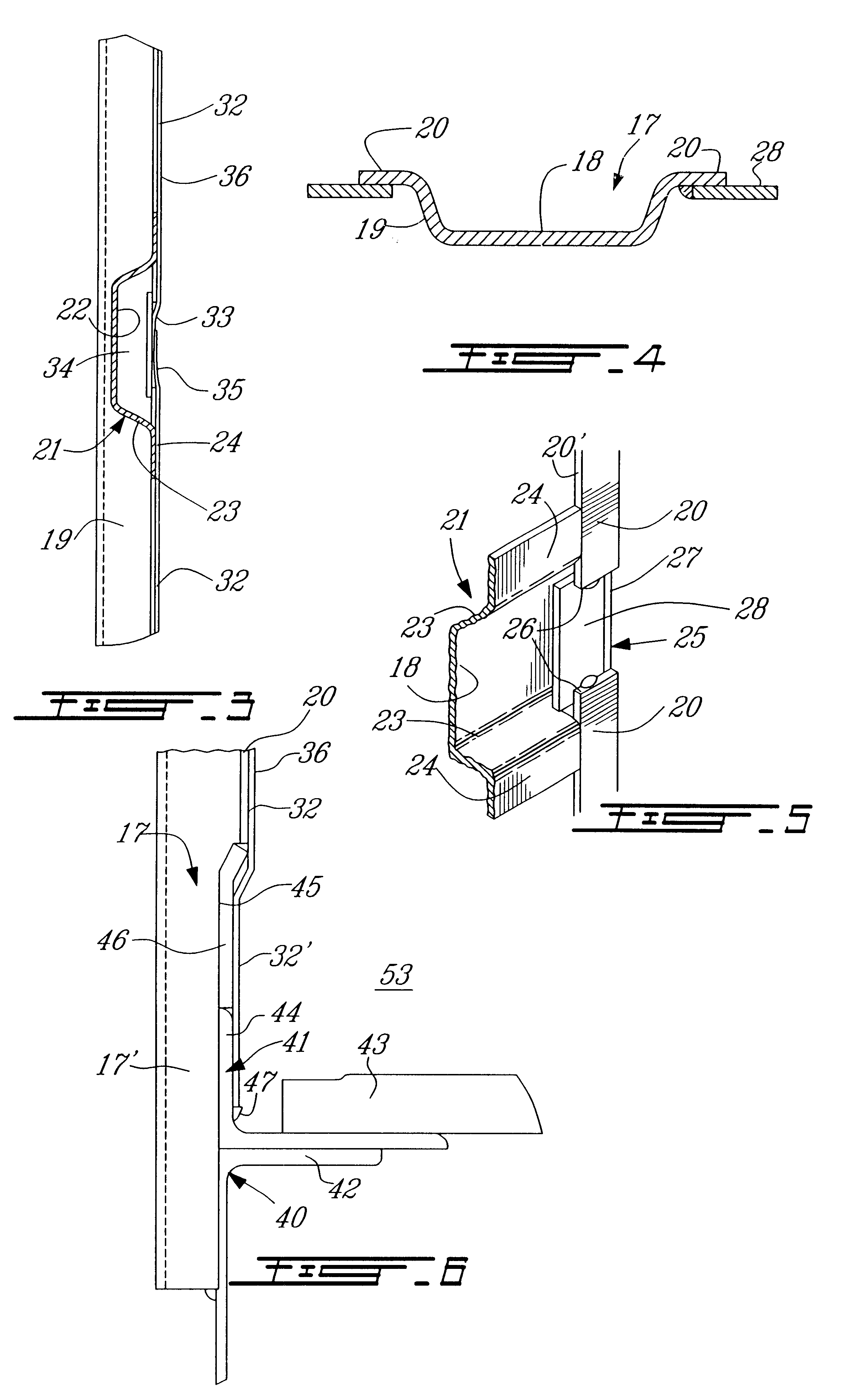
Referring now to the drawings and more particularly to FIG. 1, there is shown generally at 10 a railway box car constructed in accordance with the present invention. The railway box car 10 consists essentially of a body structure 11 which is supported on trucks 12. The body structure 11 is defined by a flooring structure 13, a side wall structure 14 secured on both longitudinal sides of the flooring structure 13 and an end frame structure 15 at opposed transverse ends of the flooring structure 13 and secured between opposed ends of the side wall structure 14. A roof frame 16 is secured over the side and end walls. of particular importance to the railway box car of the present invention is the construction of its side wall structure. This side wall structure 14 will now be described with further reference to FIGS. 2 to 5. The side wall structure 14 is formed by a plurality of spaced-apart vertical side posts 17. The vertical side posts 17, as shown in FIG. 4, are hat-shaped in cross-...


PUM


Abstract

An improved railway car body structure is described. One of the features of the box car is that the longitudinal side walls are formed by a plurality of spaced apart vertical side posts which are hat-shaped in cross-section and define a bottom wall portion, opposed side walls and opposed end flanges extending in a common plane. Horizontal structural stiffeners are secured between the vertical side posts. The stiffeners define a recessed wall portion aligned with a recessed formation formed in the opposed end flanges of the vertical side posts. Ferrous sheet members are secured to the side wall and also to the end frames by welds disposed in the recess wall portion of the stiffeners and recessed formation of the vertical posts to form flush, unobstructed, inner side and end walls of the railway car. A new roof structure is also described and incorporates improved skylight designs.

Description

The present invention relates to an improved railway box car body structure and particularly to a structure wherein the longitudinal side walls are comprised of a plurality of vertical side posts and structural horizontal stiffeners interconnected in such a way as to accommodate a recessed horizontal interconnection of ferrous sheet members to form flush inner side surfaces which are free of any obstructing elements not to damage shifting cargo transported by the box car.U.S. Pat. No. 5,287,814 describes a car body for a railway car and particularly for passenger cars and wherein the side wall structure is formed with steel posts, stiffeners, rails, window heads and these are joined by brackets and outer side plates secured to the frame members by blind rivets.U.S. Pat. No. 3,866,546 relates to a box car end structure which is the type of railway rolling stock cars that the present invention relates. This patent typifies some of the problems that the present invention wishes to over...

Claims


Application Information

Patent Timeline
IPC IPC(8): B61D17/04B61D17/12B61D17/08
CPCB61D17/08B61D17/12
Inventor WINSOR, ROBERT B.PHARAND, JEAN-FRAN.CEDILLA.OISWOOLLAM, RONALD F.DRATVA, JOHN-JOHNIORIO, JEANTHOMAN, MELL R.
Owner IEC HOLDEN INC
Learn More