
Ink ejector

Inactive Publication Date: 2002-07-16
BROTHER KOGYO KK
View PDF13 Cites 26 Cited by
  • Summary
  • Abstract
  • Description
  • Claims
  • Application Information

AI Technical Summary

Benefits of technology

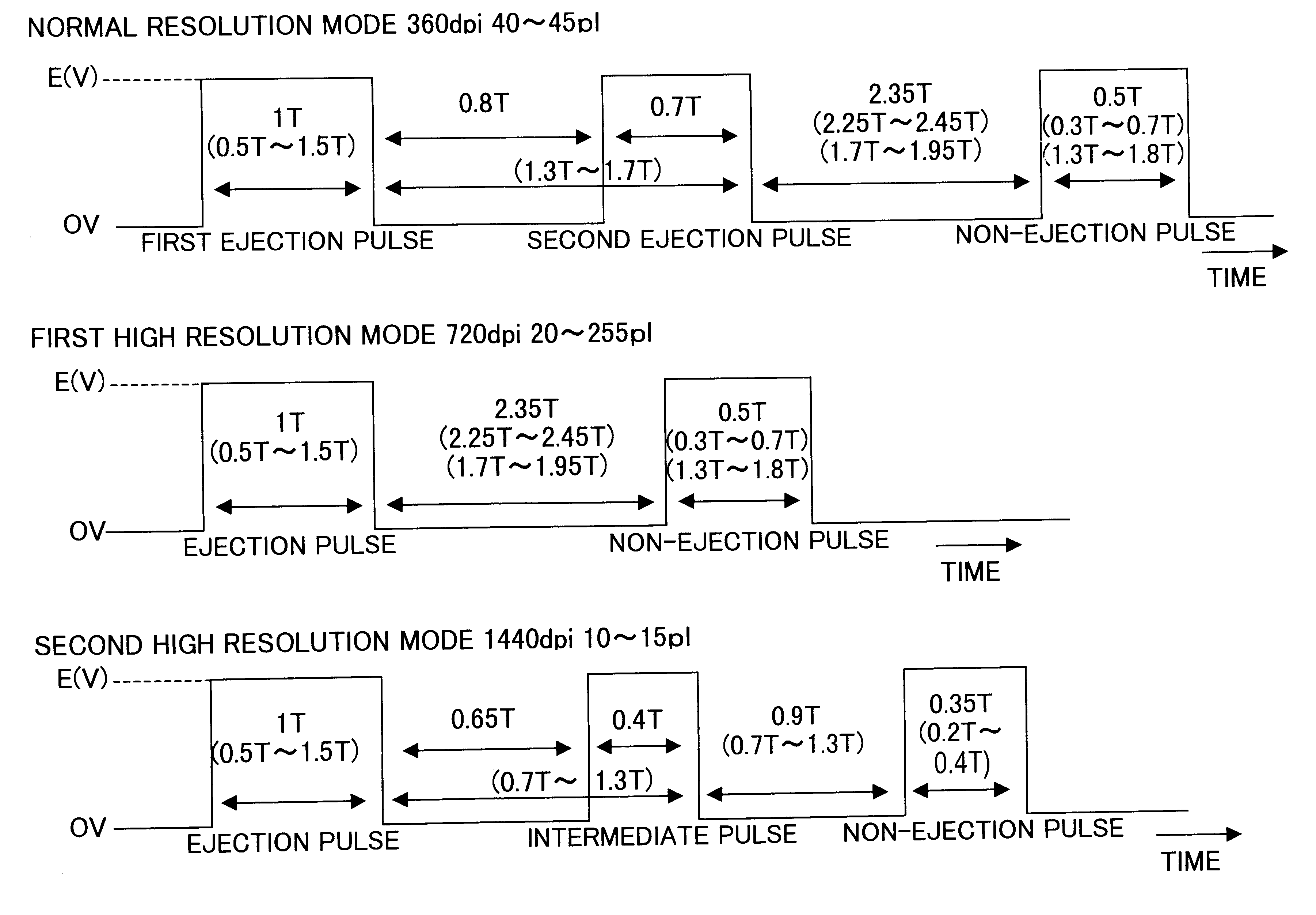
In accordance with a setting of resolution, which represents the clearness of an image to be printed, the controller can change the number of ejection pulses for application to the actuator. If the resolution specified by the user is lower, the controller increases the number of ejection pulses. This increases the frequency of driving the actuator, and therefore the number of ejected ink droplets increases. As a result, the total volume of the droplets increases, and therefore they form a larger spot or area on a recording medium. If the specified resolution is higher, the controller decreases the number of ejection pulses, decreasing the number of ejected ink droplets. Consequently, the droplets form a smaller spot for finer printing. It is therefore possible to make a distinct difference in dot density between settings of resolution.
By the conventional method of adjusting the resolution by controlling the voltage for application to the actuators, the ratio of the volume of each ink droplet for normal resolution to that for high resolution can be only 10 / 7. The ejector according to the invention can increase the volume ratio up to 2 / 1. This makes it possible to make a distinct difference in dot density between settings of resolution. It is therefore possible to achieve printing as the users need.
The second resolution may include a high resolution and a very high (super) resolution. When the very high setting is chosen, the controller applies to the actuator the single ejection pulse for ejecting an ink droplet to print one dot and an auxiliary pulse of voltage for making the droplet smaller. When the very high setting is chosen, it is possible to eject an ink droplet smaller in volume than when the high setting is chosen. This can provide higher resolution as the users prefer and more scope or room for choice of resolution.
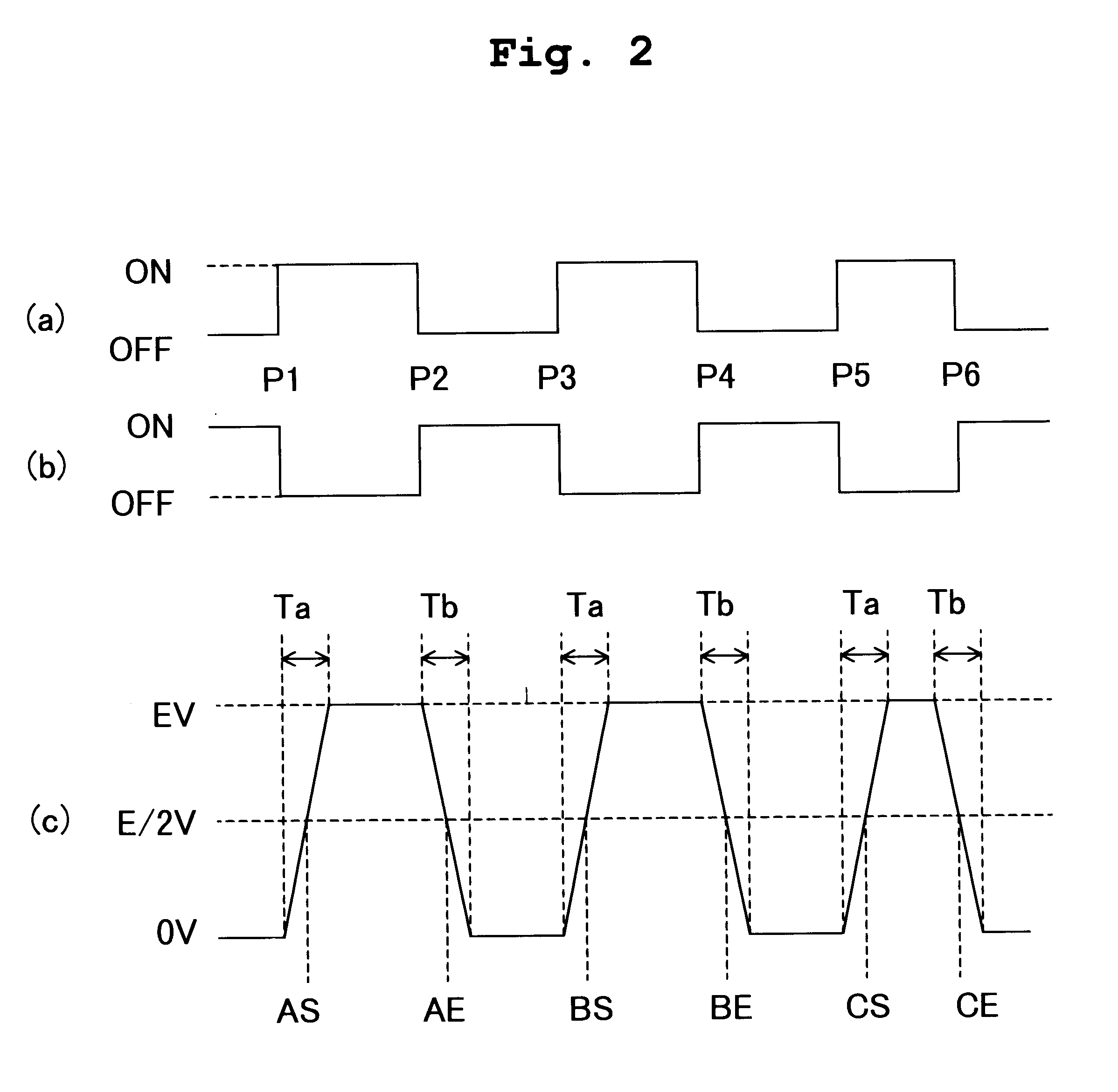
After applying the ejection pulse or pulses or the auxiliary pulse to the actuator, the controller may apply to the actuator a non-ejection pulse for varying the volume of the channel to cancel the pressure wave vibration in the channel. The non-ejection pulse prevents the ink head from unintentionally ejecting the ink. Therefore, without waiting until the pressure wave in the channel damps, the controller can quickly apply to the actuator the ejection pulse or pulses for printing the next dot. As a result, it is possible to improve the printing speed.

Problems solved by technology

However, the ratio of the droplet volume in the normal resolution mode to that in the high resolution mode is about 10 / 7, and therefore the difference in droplet volume is too small.
Excessive vibration of the meniscus may eject ink at wrong times or spatter ink droplets in fine particles, blurring the printing.
In this case, the meniscus recedes deep into the channel, forming air bubbles in it, which may render the ejection difficult.
If the ejection speed is low, the ejected droplets may fly in wrong directions onto wrong spots under the influence of wind or the like.
If the ejection speed is lower, the main drop and the satellites may fly onto more displaced or dislocated spots, blurring the printing.

Method used


Image

  • Ink ejector
  • Ink ejector
  • Ink ejector

Examples


Embodiment Construction

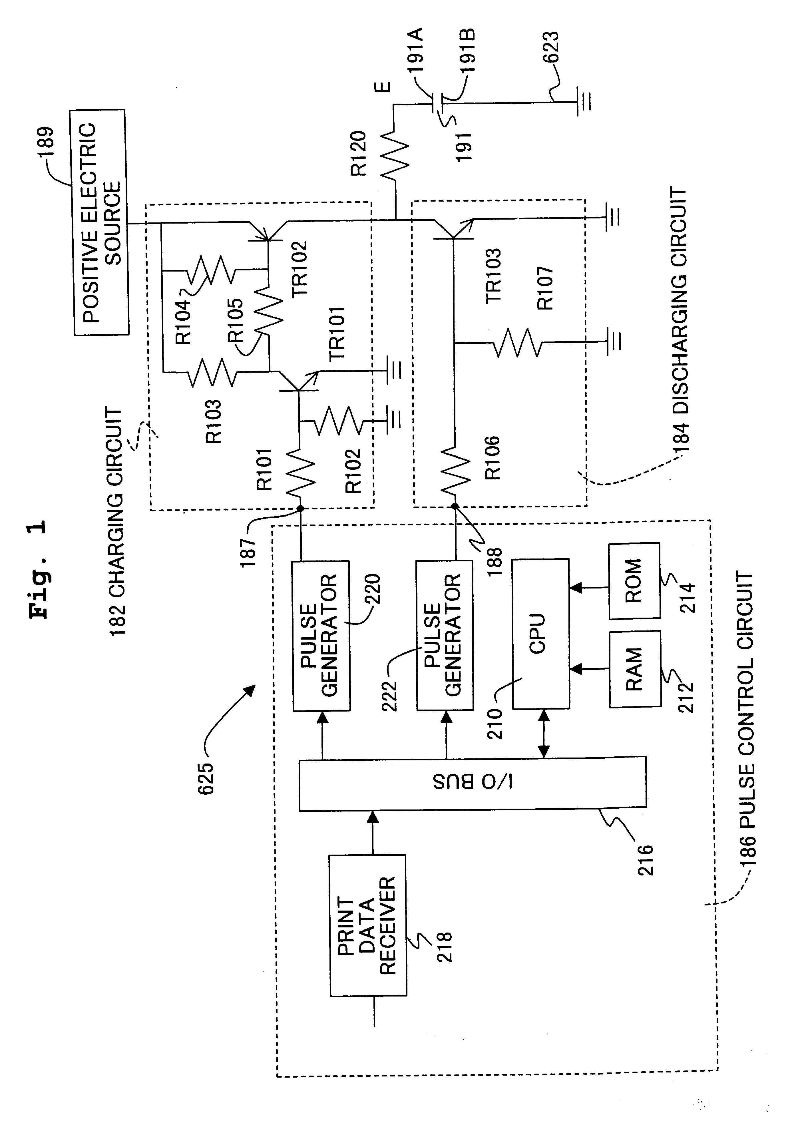
With reference to FIGS. 7A and 7B, an ink ejector 600 embodying the invention includes a base wall 601 and a top wall 602, between which eight shear mode actuator walls 603a-603h extend. The actuator walls 603a-603h each consist of an upper part 605 and a lower part 607, which are made of piezo-electric material. The wall parts 605 and 607 are bonded to the top wall 602 and the base wall 601, respectively, and polarized in the opposite directions of arrows 609 and 611, respectively. The actuator walls 603a, 603c, 603e and 603g pair with the actuator walls 603b, 603d, 603f and 603h, respectively, to define a channel 613 between each pair of actuator walls. The actuator walls 603b, 603d and 603f pair with the actuator walls 603c, 603e and 603g, respectively, to define a space 615 between each pair of actuator walls. The three spaces 615 are narrower than the four channels 613.

At one end of the channels 613 is secured a nozzle plate 617 formed with nozzles 618 each communicating with o...


PUM


Abstract

An ink ejector includes an ink jet head. The head has ink channels each defined between a pair of actuator walls. The head also has nozzles each communicating with one of the channels. In accordance with a print instruction, a controller applies to the appropriate actuator walls one or two ejection pulses of voltage depending on the resolution specified by the instruction. Each ejection pulse increases the volume of the associated channel once and decreases it subsequently to eject an ink droplet from the channel through the associated nozzle. In a normal resolution mode, two such ejection pulses are applied. In a first high resolution mode, one such ejection pulse is applied. In a second high resolution mode, one such ejection pulse is followed by an auxiliary pulse for making the droplet smaller. The ratio of the total volume of the two droplets in the normal resolution mode to the volume of the droplet in the first high resolution mode is approximately 2 / 1. The ratio of the droplet volume in the first high resolution mode to that in the second high resolution mode is approximately 2 / 1. This enables the difference in dot density between the resolution modes to be distinct for good printing.

Description

1. Field of the InventionThe present invention relates to an ink ejector for forming an image on a recording medium such as recording paper by ejecting ink from a number of channels in accordance with a print instruction.2. Description of Related ArtOf all non-impact printers, ink jet printers have simple principles and can easily perform multiple gradation and colorization printing. Drop-on-demand ink jet printers eject only droplets of ink for printing. Ink jet printers of this type are coming rapidly into wide use because of high ejection efficiency and low running costs.For example, U.S. Pat. No. 4,879,568, U.S. Pat. No. 4,887,100, U.S. Pat. No. 4,992,808, U.S. Pat. No. 5,003,679 and U.S. Pat. No. 5,028,936, which correspond to Japanese Patent Application Laid-Open No. 63-247051, disclose ink ejectors of the shear mode type for use in "drop-on-demand" printers. Each of the ejectors includes a controller and an ink jet head. The head has actuator walls of piezo-electric material,...

Claims


Application Information

Patent Timeline
IPC IPC(8): B41J2/045B41J2/01B41J2/055B41J2/205
CPCB41J2/04541B41J2/04551B41J2/04573B41J2/04581B41J2/04588B41J2/04591B41J2/04593B41J2/04595B41J2/04596B41J2202/10
Inventor TAKAHASHI, YOSHIKAZU
Owner BROTHER KOGYO KK
Learn More