
Hydrocyclone and process for removing foreign substances from a liquid

a technology of foreign substances and hydrocyclones, applied in separation processes, wet separation, centrifugal force sediment separation, etc., can solve the problems of hydrocyclones not being able to remove foreign substances, stoppages cannot always be prevented,

Inactive Publication Date: 2002-06-04
VOITH PATENT GMBH
View PDF3 Cites 10 Cited by
  • Summary
  • Abstract
  • Description
  • Claims
  • Application Information

AI Technical Summary

Benefits of technology

In the case of hydrocyclones equipped according to the invention, a layer is provided at critical locations that changes its appearance, e.g., its color, in accordance with temperature changes in the area of interest. In this manner, the present invention utilizes the fact that critical accumulation of substances that may cause stoppages, e.g., foreign substances, produces or creates temperature changes. The reason is that the temperature of the liquid to be cleaned almost always deviates from the ambient temperature. For example, the temperature is higher at locations at which the liquid is flowing by the wall of the flow device, thereby producing heat. As a consequence, an approximately uniform temperature adjusts or occurs during the undisturbed operation of the flow device. However, if the accumulation of foreign substances becomes so great that the flow is partially brought to a standstill, i.e., a stoppage is imminent, the flow device begins to cool at this location toward the ambient temperature. As a result, a local temperature change can be viewed as an indicator of a stoppage, e.g., that has begun or that has already occurred. In this way, it is possible to prevent or quickly eliminate operating malfunctions. Tests determine the to-be-prescribed extent of the temperature deviation at which a critical accumulation of foreign substances is present. It depends, among other things, on the level and constancy of the temperature of the liquid in the flow device.
In this manner, it is very easy to monitor an entire battery of hydrocyclones. No lines are required for the power supply or measuring data and measuring strips that change color as a function of temperature are inexpensive and easy to handle. Such measuring strip are used as thermometers, which, though easy to read, are often slow-reacting and imprecise. However, they are ideal for the instant invention to provide "at a glance" detection. This is particularly advantageous with the conventionally large number of hydrocyclones in a facility. Moreover, it is not necessary to determine or detect an exact numerical value of the temperature.
In accordance with another feature of the present invention, the color layer can be adapted to change color when an accumulation of foreign substances substantially prevents the flow of the liquid to be cleaned in the stoppage-hazard zone.

Problems solved by technology

However, due to frequently changing operating conditions, such as the dirt load, the occurrence of stoppages cannot always be prevented.
The formation of stoppages has at least two considerable disadvantages: The hydrocyclone will then no longer fulfill its task, i.e., will no longer be able to remove foreign substances; and in some cases, high local wear occurs on the hydrocyclone that is caused by the heavy parts rotating at one location and thus abrading the wall of the hydrocyclone.
However, because many facilities contain a large number of hydrocyclones, this can be expensive.
However, if the accumulation of foreign substances becomes so great that the flow is partially brought to a standstill, i.e., a stoppage is imminent, the flow device begins to cool at this location toward the ambient temperature.
Such measuring strip are used as thermometers, which, though easy to read, are often slow-reacting and imprecise.

Method used


Image

  • Hydrocyclone and process for removing foreign substances from a liquid
  • Hydrocyclone and process for removing foreign substances from a liquid
  • Hydrocyclone and process for removing foreign substances from a liquid

Examples


Embodiment Construction

The particulars shown herein are by way of example and for purposes of illustrative discussion of the embodiments of the present invention only and are presented in the cause of providing what is believed to be the most useful and readily understood description of the principles and conceptual aspects of the present invention. In this regard, no attempt is made to show structural details of the present invention in more detail than is necessary for the fundamental understanding of the present invention, the description taken with the drawings making apparent to those skilled in the art how the several forms of the present invention may be embodied in practice.

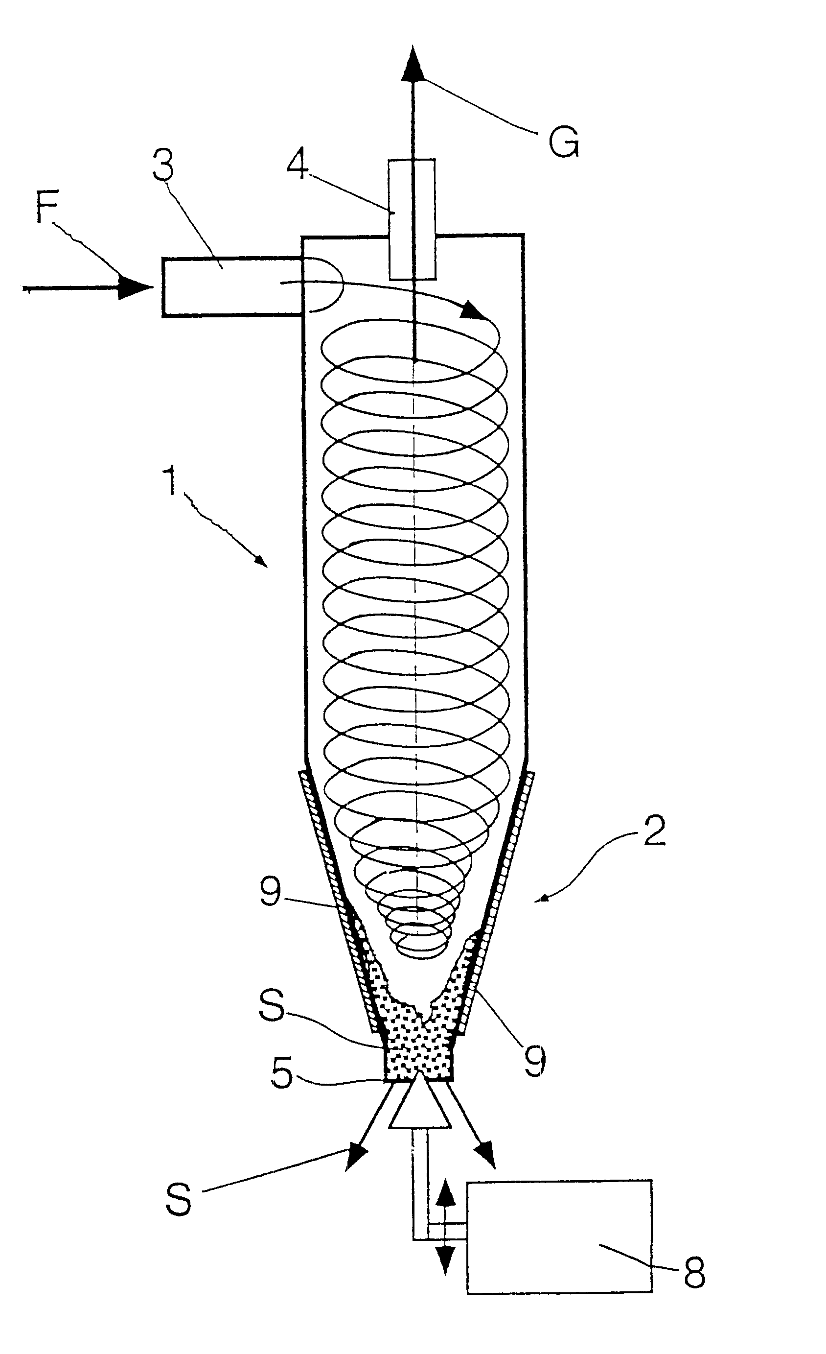
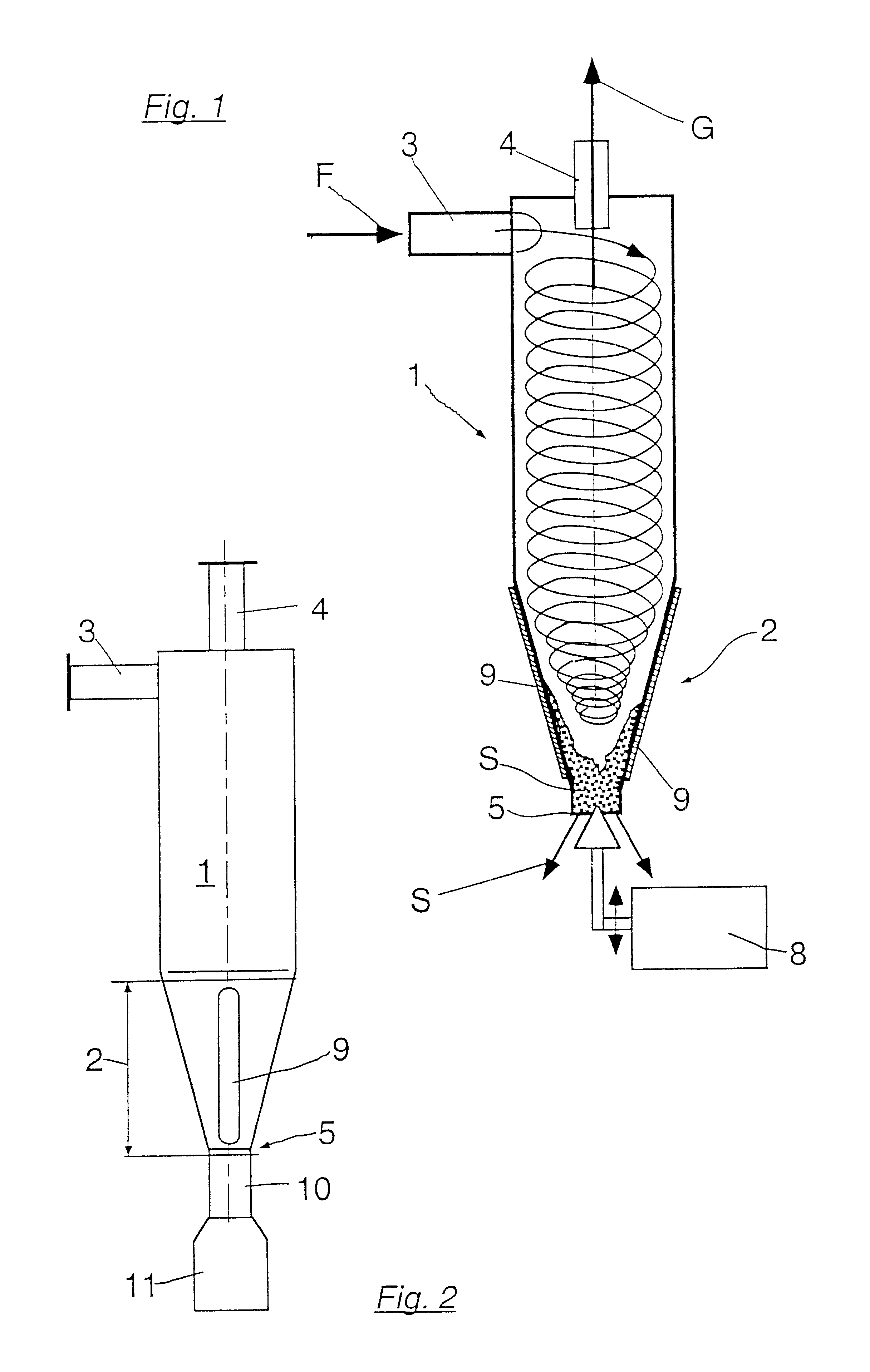
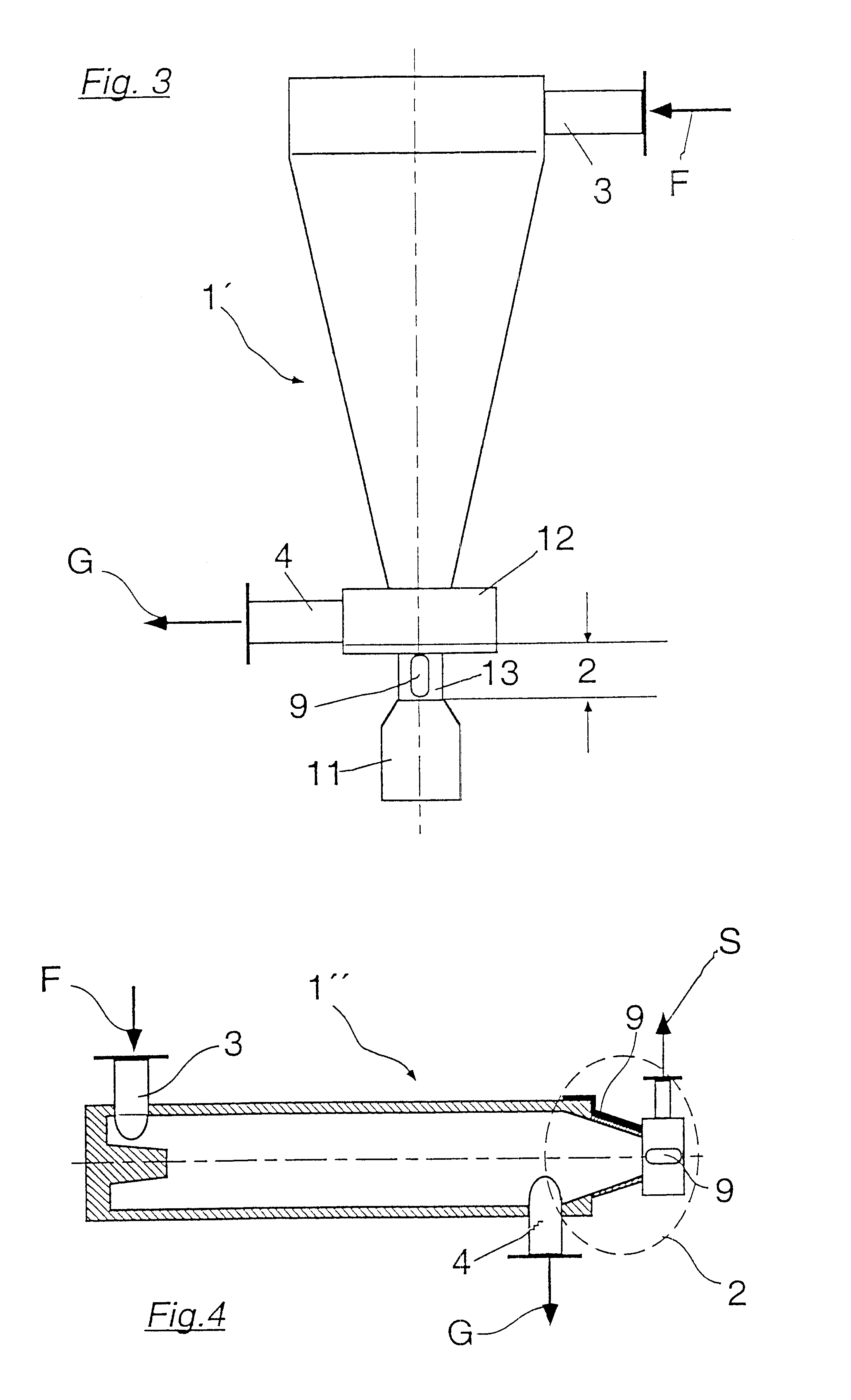
FIG. 1 illustrates a hydrocyclone 1 intended to remove heavy parts with an inlet 3 for the liquid F to be cleaned. As is known, liquid F is set into rotation in hydrocyclone 1, whereby centrifugal forces occur which lead to the foreign substances being centrifuged onto the inside wall of hydrocyclone 1. Accepted stock G cleaned...


PUM

PropertyMeasurementUnit
temperatureaaaaaaaaaa
temperaturesaaaaaaaaaa

Abstract

Hydrocyclone and process for removing foreign substances from a liquid to be cleaned. The hydrocyclone includes at least one inlet for the liquid to be cleaned, at least one accepted stock outlet for the cleaned liquid, and at least one reject opening for foreign substances removed from the liquid to be cleaned. The at least one reject opening includes at least one stoppage-hazard zone, and a color layer is coupled to an exterior wall of the hydrocyclone. The color layer changes appearance in accordance with different temperatures. The process includes introducing the liquid to be cleaned into a hydrocyclone through at least one inlet, discharging cleaned liquid from the hydrocyclone through at least one accepted stock outlet, and discharging the foreign substances from the hydrocyclone through at least one reject opening. The process also includes detecting one of a potential and an actual stoppage in a stoppage-hazard zone of the at least one reject opening by monitoring a color change of a color layer coupled to an exterior wall of the hydrocyclone.

Description

The present application claims priority under 35 U.S.C. .sctn.119 of German Patent Application No. 199 30 088.7, filed on Jun. 30, 1999, the disclosure of which is expressly incorporated by reference herein in its entirety.1. Field of the InventionThe present invention relates to a hydrocyclone for removing foreign substances from a liquid which includes at least one inlet for the liquid to be cleaned, at least one accepted stock outlet for the cleaned liquid, and at least one reject opening for foreign substances, which has at least one stoppage-hazard zone.2. Discussion of Background InformationAs is generally known, hydrocyclones are used for concentrating and draining off liquids containing foreign substances using strong centrifugal forces. They are frequently used in the removal of small metal parts, glass splinters, and sand from fibrous stock suspensions. As a result of the accumulation of foreign substances in specific areas of the hydrocyclone, stoppages are to be expected...

Claims


Application Information

Patent Timeline
Patent Type & Authority Patents(United States)
IPC IPC(8): B04C11/00D21D5/00D21D5/24
CPCD21D5/24B04C11/00
Inventor HARTMANN, ROLF
Owner VOITH PATENT GMBH
Learn More