
Fuel reformer for mounting on a vehicle

a technology for reformers and vehicles, applied in the direction of fuel reformers, electrochemical generators, combustion air/fuel air treatment, etc., can solve the problems of inadequate reforming performance, various constraints, and the reformer is not suitable for mounting on the vehicl

Inactive Publication Date: 2002-05-21
TOYOTA JIDOSHA KK
View PDF15 Cites 55 Cited by
  • Summary
  • Abstract
  • Description
  • Claims
  • Application Information

AI Technical Summary

Benefits of technology

In accordance with this aspect of the present invention, by making the material gas flow in a direction approximately parallel to the floor surface of the vehicle for the reforming reaction, the fuel reformer for mounting on a vehicle becomes more suitable for mounting on a vehicle which has a larger degree of freedom in the horizontal direction than in the vertical direction. That is, when the reformer is mounted on a vehicle having its parallel dimension larger than its vertical direction, such as a small passenger car, a reaction container (catalyst layer) can be extended so that there is a sufficiently long contact time between the raw material gas and the catalyst. As a result, the performance of the fuel reformer can be improved.
In this aspect of the fuel reformer for mounting on a vehicle according to the present invention where the vaporization, reforming, and carbon monoxide reducing sections are each provided as a separate unit, at least one of the unitized vaporization, reforming, and carbon monoxide sections can be constructed from a plurality of parts, each of which is provided as a separate unit. In this manner, assembly of a plurality of separate units can be simplified and the operational ease during manufacturing can be improved. In this aspect of the fuel reformer for mounting on a vehicle according to the present invention, the reforming section can comprise a flow rate unifying section for making the flow rate of the raw material gas uniform, a raw material gas heating section for heating the raw material gas, and a catalyst section having a catalyst for reforming supplied raw material gas, each of which is separately provided as a unit.

Problems solved by technology

However, this type of reformer suffers in that the reformer is not suitable for mounting on a vehicle, especially a small passenger car.
When the reforming reaction is performed by making the raw material gas flow vertically, in some cases, contact time of sufficient length for contact between gas and the catalyst cannot be obtained, resulting in inadequate reforming performance.
When any apparatus, including, but not limited to, a fuel reformer, is mounted on a vehicle, various constraints are generated because space in the vehicle is limited and each space plays a particular role.
Due to these constraints, some problems arise that are not applicable when the apparatus is not mounted on a vehicle.
Because a monolithic catalyst is formed by carrying catalysts on a honeycomb shaped carrier having various types of cross sections, it does not suffer in having spaces in an upper portion when the reforming section is horizontally placed, a problem which occurs in catalysts carried on pellets.

Method used


Image

  • Fuel reformer for mounting on a vehicle
  • Fuel reformer for mounting on a vehicle
  • Fuel reformer for mounting on a vehicle

Examples


Embodiment Construction

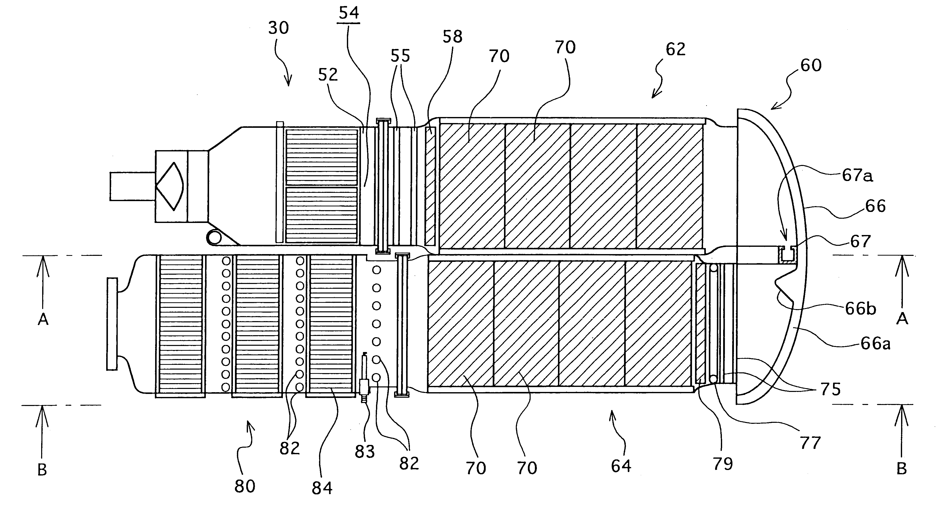
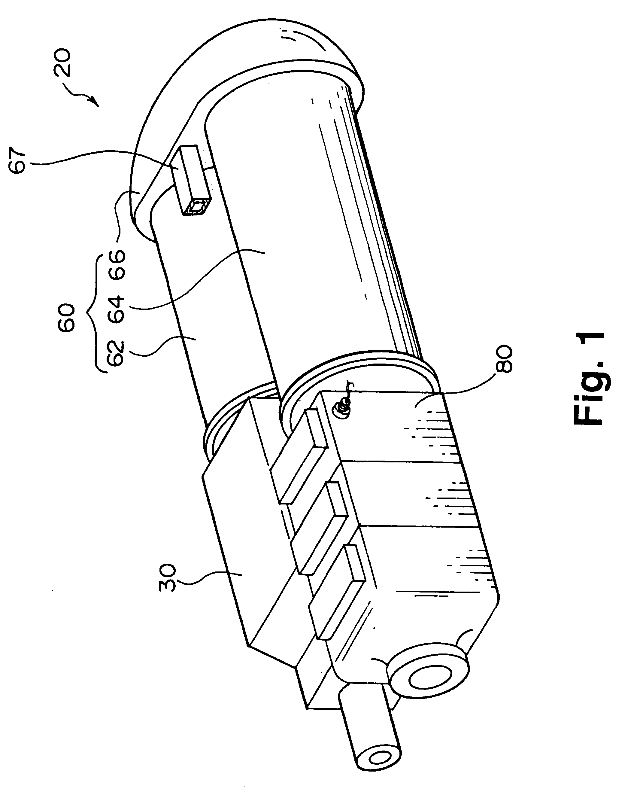
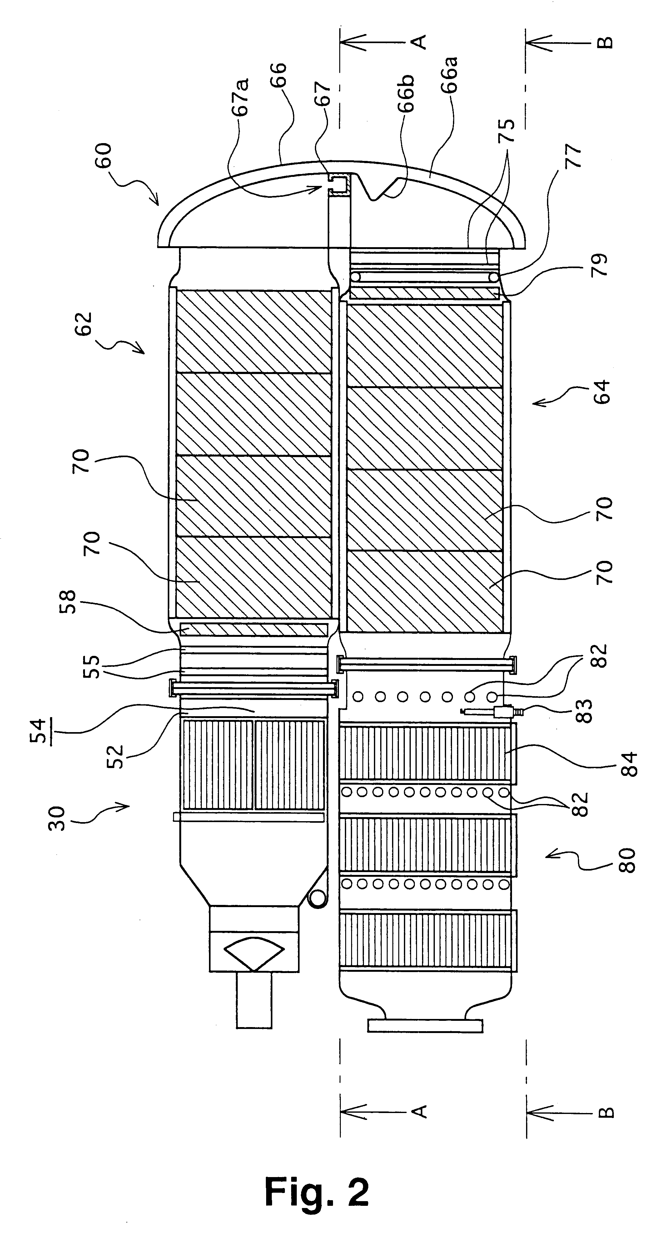
The preferred embodiments of the present invention are described next. FIG. 1 is a structural diagram schematically showing a structure of a fuel reformer 20 for mounting on a vehicle of one embodiment of the present invention. FIG. 2 is a cross sectional diagram showing a cross section of the fuel reformer 20 of the embodiment in the horizontal direction. FIG. 3 is a diagram schematically showing the gas flow in the fuel reformer 20 of the embodiment. As shown in the figure, the fuel reformer 20 for mounting on a vehicle according to the embodiment comprises a vaporization section 30 for vaporizing reforming raw material formed from water and methanol acting as a hydrocarbon fuel, a reforming section 60 for reforming raw material gas formed by supplying air as an oxygen-containing gas to the vaporized reforming raw material into a hydrogen-rich reformed gas, and a CO reducing section 80 for reducing the carbon monoxide concentration in the reformed gas so that a fuel gas which is r...


PUM


Abstract

A fuel reformer suited for mounting on a vehicle is provided. A raw material gas containing methanol and water is vaporized at a vaporization section 30. The vaporized gas flows horizontally to a reforming section 60 with monolithic catalyst 70. The reforming section is divided into two sides, a front side 62 and a rear side 64, with an interconnecting pipe 66 bent at 180 degrees, for connecting the front and rear sides. By making the material gas flow horizontally, even when the reformer is mounted to a vehicle which has a larger space in its horizontal direction than in its vertical direction, especially a small passenger car, the contact time period between gas and catalyst can be extended. By bending the reforming section by 180 degrees, the size of the reformer can be reduced so that the reformer is suited for mounting on a vehicle having limited space. Because the vaporization section 30 and the CO reducing section 80 can be placed adjacent to each other, by using heat generated at the CO reducing section, the heat loss during pre-heating of the methanol and water can be reduced.

Description

1. Field of the InventionThe present invention generally relates to a fuel reformer for mounting on a vehicle and more particularly to a reformer for mounting on a vehicle for reforming hydrocarbon fuel to a hydrogen-containing gas using water vapor.2. Description of the Prior ArtConventionally, it has been proposed to use a type of fuel reformer for mounting on a vehicle which performs a reforming reaction by causing raw material gas to flow in a vertical direction (for example, refer to Japanese Patent Laid-Open Publication No. Hei 4-200737). In this apparatus, the reforming reaction is performed by spirally wrapping two plate members around a vertically standing, cylindrically-shaped housing to form a catalyst layer and making the raw material gas flow vertically. The fuel reformer is provided around the center of a vehicle, on the left side or on the right side.However, this type of reformer suffers in that the reformer is not suitable for mounting on a vehicle, especially a sma...

Claims


Application Information

Patent Timeline
IPC IPC(8): B01J19/24B01J8/04C01B3/38C01B3/32C01B3/00C01B3/58H01M8/06F02M27/02F02D19/02
CPCB01J8/0496C01B3/323C01B3/38C01B3/583H01M8/0631B01J19/2485Y02E60/50B01J2208/00061B01J2208/00309B01J2208/0053B01J2208/00716B01J2219/002B01J2219/00231C01B2203/0244C01B2203/044C01B2203/047C01B2203/0811C01B2203/0822C01B2203/0827C01B2203/0838C01B2203/0844C01B2203/085C01B2203/0866C01B2203/0883C01B2203/1023C01B2203/1076C01B2203/1082C01B2203/1217C01B2203/1223C01B2203/1235C01B2203/1276C01B2203/1288C01B2203/143C01B2203/1604C01B2203/1609C01B2203/1619C01B2203/1633C01B2203/1638C01B2203/169C01B2203/1695C01B2203/82Y02P20/10
Inventor ISOGAWA, RYUHEINOBATA, YASUHIROKONDO, MASATSUNEOGINO, SHIGERUKIMURA, KENJITAKI, MASAYOSHINISHIMURA, AKIHISAYAMAOKA, MASAAKINEGISHI, YOSHIMASATAGUCHI, HIDEOSAITO, NORIHIKOTAKUMI, ATSUSHI
Owner TOYOTA JIDOSHA KK
Learn More