
Video Display and manufacturing method therefor

a technology of video display and manufacturing method, which is applied in the field of video display, can solve the problems of small thickness of display panel and printed wiring board, and achieve the effect of reducing thickness

Inactive Publication Date: 2002-04-30
SONY CORP
View PDF9 Cites 11 Cited by
  • Summary
  • Abstract
  • Description
  • Claims
  • Application Information

AI Technical Summary

Benefits of technology

It is accordingly an object of the present invention to provide a video display which can display a large-sized video image with no discontinuities and can be reduced in thickness.
In accordance with an aspect of the present invention, there is provided a video display comprising a display panel having a plurality of anodes and cathodes arranged orthogonally to each other so as to form grids; a printed wiring board having a drive circuit with wirings for driving the display panel and a plurality of bumps for electrically connecting the wirings of the drive circuit to the anodes and the cathodes; and an adhesive layer for bonding the display panel and the printed wiring board to form a multilayer structure. That is, the anodes and the cathodes of the display panel are electrically connected through the bumps to the wirings of the printed wiring board, and the display panel and the printed wiring board are bonded together through the adhesive layer. With this structure, the display panel is not required to have any dedicated region for electrically connecting the anodes and the cathodes of the display panel to the drive circuit for driving the display panel. Further, the total thickness of the display panel and the printed wiring board is small.
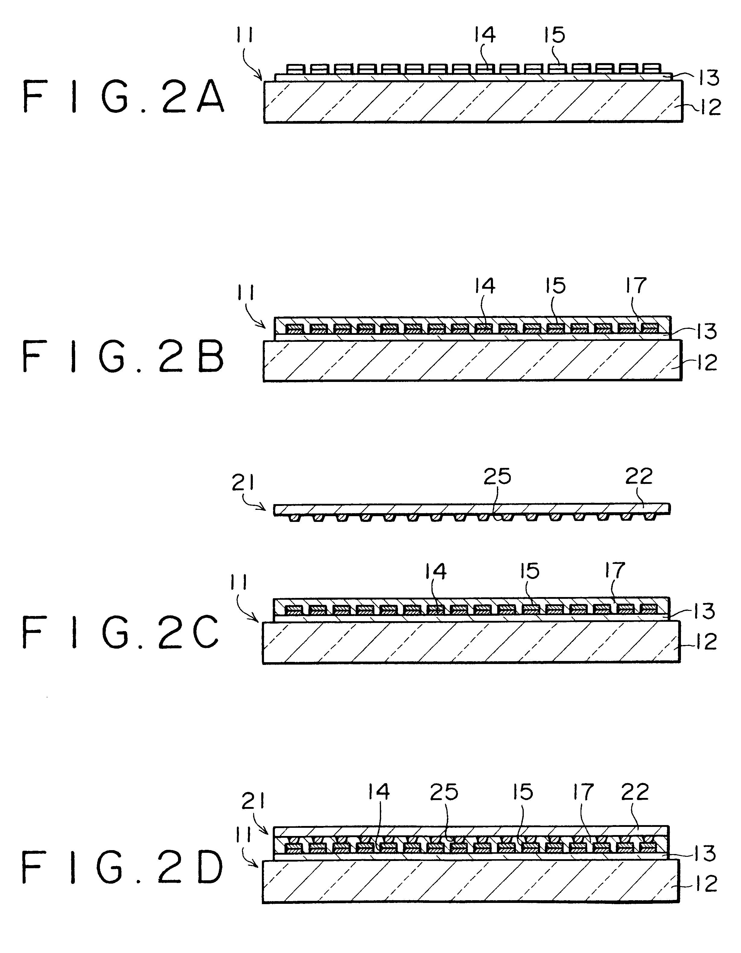
In accordance with another aspect of the present invention, there is provided a manufacturing method for a video display, comprising the steps of preparing a display panel having a plurality of anodes and cathodes arranged orthogonally to each other so as to form grids; preparing a printed wiring board having a drive circuit with wirings for driving the display panel and a plurality of bumps for electrically connecting the wirings of the drive circuit to the anodes and the cathodes; forming an adhesive layer on any one of one surface of the display panel on which the anodes and the cathodes are provided and one surface of the printed wiring board on which the bumps are provided; and electrically connecting the anodes and the cathodes through the bumps to the wirings and bonding the display panel through the adhesive layer to the printed wiring board. That is, the anodes and the cathodes of the display panel and the wirings of the printed wiring board are electrically connected together through the bumps, and the display panel and the printed wiring board are bonded together through the adhesive layer. Accordingly, it is possible to manufacture a video display in which the display panel is not required to have any dedicated region for electrically connecting the anodes and the cathodes of the display panel to the drive circuit for driving the display panel, and the total thickness of the display panel and the printed wiring board can be reduced.

Problems solved by technology

Further, the total thickness of the display panel and the printed wiring board is small.

Method used


Image

  • Video Display and manufacturing method therefor
  • Video Display and manufacturing method therefor
  • Video Display and manufacturing method therefor

Examples


Embodiment Construction

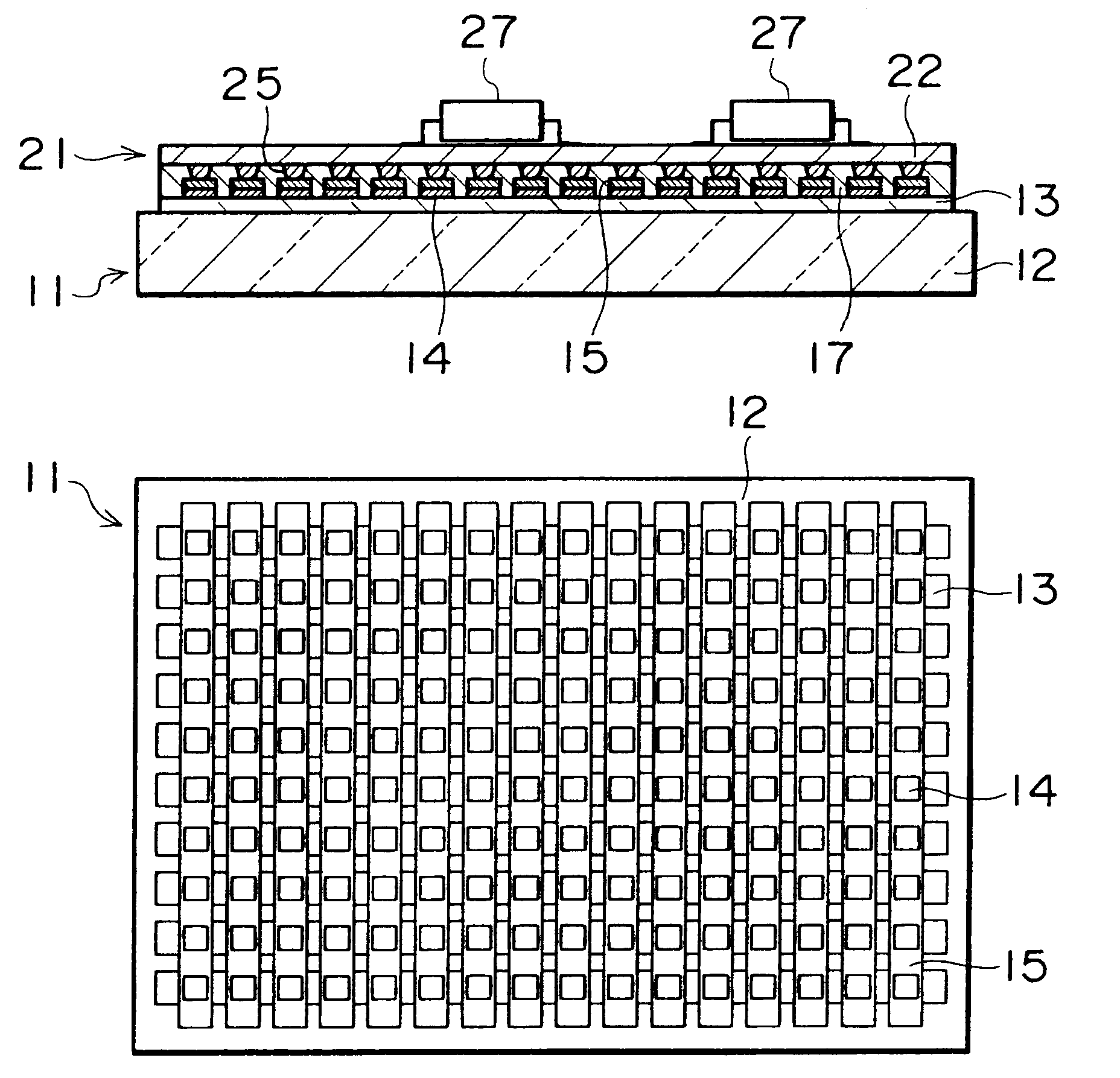
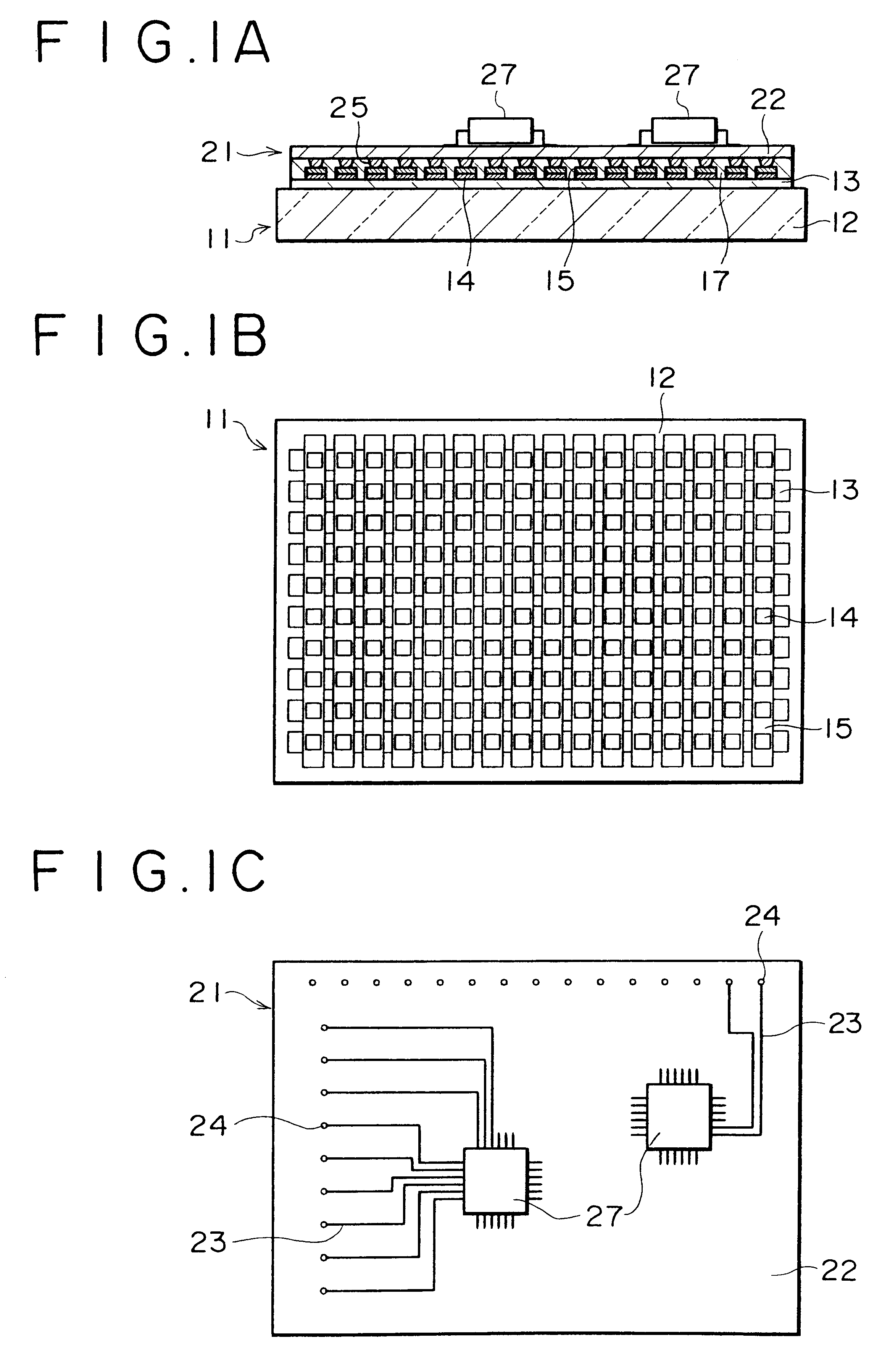
There will now be described a preferred embodiment of the present invention applied to an active matrix drive type EL video display and its manufacturing method with reference to FIGS. 1A to 4. In manufacturing the EL video display shown in FIGS. 1A to 1C, an EL display panel 11 is first prepared by sequentially forming anodes 13, EL phosphor layers 14, an insulating layer (not shown), and cathodes 15 on one surface of a glass substrate 12 which surface is opposite to the display surface of the EL display panel 11, by vapor deposition, CVD, etc. as shown in FIG. 2A.

As shown in FIG. 1B, the anodes 13, the EL phosphor layers 14, and the cathodes 15 are formed substantially uniformly on the glass substrate 12, so that the EL display panel 11 has no L-shaped region dedicated for electrical connection as in the related art configuration shown in FIG. 5A. As usual, the anodes 13 are formed by vapor deposition of an aluminum layer or a chromium layer, for example, on an ITO (indium-tin oxi...


PUM


Abstract

Disclosed herein are a video display and a manufacturing method therefor, more particularly, there is provided a video display including a display panel having a plurality of anodes and cathodes arranged orthogonally to each other so as to form grids, a printed wiring board having a drive circuit with wirings for driving the display panel and a plurality of bumps for electrically connecting the wirings of the drive circuit to the anodes and the cathodes, and an adhesive layer for bonding the display panel and the printed wiring board to form a multilevel structure. With this structure, a large-sized video image with no discontinuities can be displayed, and the thickness of the video display can also be reduced.

Description

BACKGROUND OF THE INVENTIONThe present invention relates to a video display having a display panel provided with anodes and cathodes arranged orthogonally to each other to form grids, and also to a manufacturing method for such a video display.FIG. 5A is a plan view of a related art electroluminescent (EL) display panel in an active matrix drive type EL video display, and FIG. 5B is a cross section view taken along the line B--B in FIG. 5A. As shown in FIGS. 5A and 5B, the EL display panel 11 includes a glass substrate 12, a plurality of anodes 13 formed on one surface of the glass substrate 12 opposite to the display surface of the EL display panel 11 so as to be arranged in rows, for example, a plurality of EL phosphor layers 14 formed in the form of matrix, an insulating layer (not shown) formed on the EL phosphor layers 14, and a plurality of cathodes 15 formed on the insulating layer so as to be arranged in columns, for example.To drive the EL display panel 11, a drive circuit ...

Claims


Application Information

Patent Timeline
Patent Type & Authority Patents(United States)
IPC IPC(8): H01L25/16H05K3/36G09F9/30G09F9/40H05B33/12H05B33/26
CPCH01L25/167H05K3/363H05K3/368H01L2924/0002H01L2924/00H01J23/16H10K59/18
Inventor MATSUDA, YOSHINARISUZUKI, YOSHIOODAKE, RYOTAASAI, NOBUTOSHI
Owner SONY CORP
Learn More