Magnetron with parallel race track and modified end portions thereof

a technology of parallel race track and end portion, which is applied in the direction of electrodes, diaphragms, ion implantation coatings, etc., can solve the problems of additional problems such as arcing and plasma instability, sputtered surface contamination by shield material flakes, and costly process

Inactive Publication Date: 2002-04-23
BEKAERT ADVANCED COATINGS
View PDF3 Cites 63 Cited by
  • Summary
  • Abstract
  • Description
  • Claims
  • Application Information

AI Technical Summary

Benefits of technology

The present invention may provide the advantage that the requirement for shields can be substantially reduced. As a consequence, the cost and time consuming maintenance of these shields can be lowered, while their detrimental effect on process and product quality can be minimised. This property can be achieved by reducing the unwanted deposition of material in the region between the target and the substrate. Though excess material is still brought into the vacuum system, it can be gathered at non-critical locations, e.g. on shields between the target and the chamber walls. These shields have no direct relation with the substrate and so require less precautions, less maintenance and have no effect on the process or film quality.
In addition, shields may no longer be needed to control the film thickness uniformity over (large) substrates. In addition, the current technology of changing magnet strengths and distances, resulting in non-uniform consumption of the target material can be overcome. Precise control of sputter efficiency towards the substrate for any desired position on the substrate can be obtained with the present invention, while maintaining uniform erosion of the cylindrical target tube. This means that standard tubes can be used for every possible uniformity of erosion profile.
Furthermore, the present invention allows freedom in the configuration of the magnet assembly. The U-turns at the end of the target tube can be defined freely, allowing better control of the magnetic field. Therefore, plasma configurations in the turns and on straight zones can be achieved with which the loss of electrons is reduced. The radius of the U-turns can be varied even to values larger than the diameter of the target tube. In addition, in accordance with the present invention, the direction of manetic field adjacent the magnet assembly may be arranged perpendicular to the target surface, allowing the creation of the largest possible magnetic field strength on the target surface. Likewise, the top surface of the magnets in the magnet assembly may be arranged parallel to the target tube which enables the closest possible positioning with respect to the target, giving the largest possible magnetic efficiency.
The circular erosion groove at the end of the target tube (due to the U-turns) known from conventional devices can be reduced and in some cases even be eliminated. A spoon or elliptical (i.e. more than semi-elliptical) shape is preferred for the race-track in the end zones in accordance with one embodiment of the present invention. Even old and worn targets, for which the groove is so deep that the underlying material becomes visible, can be used again without the risk of depositing the wrong material on the substrate.
In accordance with the present invention simultaneous metal and reactive sputtering can be achieved when the race-track is arranged to traverse the back side of the cathode.

Problems solved by technology

The most important inconvenience is the formation of a groove of erosion in the target material, whereby this groove, and the plasma generating it, are often referred to as a "race track".
Typically only 30% of the target material is consumed before the target has to be changed which makes it a very costly process because of labour costs, down time as well as the expense of target materials.
During reactive sputtering (i.e. the plasma contains one or more gases that will react with the target material) using planar magnetrons, additional problems of arcing and plasma instability are encountered.
Nevertheless, large amounts of material are deposited on shields which are physically located between the target and the substrate to inhibit the deposition of target material on those locations where it is not desired.
Flakes of material from shields can contaminate the sputtered surface.
The latter solution may introduce non-uniform wear and / or consumption of the target material.
Cylindrical magnetrons have some other disadvantages which are typical for their geometry.
Known magnet assemblies do not allow optimal configuration of the magnets in an end turn which results in reduced plasma confinement and increased electron loss at both ends of the target.
Eventually, target life is limited by the depth of this groove as it is highly undesirable to deposit the underlying material of the tube onto the substrate.
As explained in WO 96 / 21750, the method according to U.S. Pat. No. 5,364,518 has the disadvantage that the wider track of the race-track in the end portions may result in instability of the plasma due to the reduced field strength and resulting electron loss caused by the wider spacing of the magnets.
The disadvantage of making the end portions pointed, in particular triangular in shape is that the radius at the point is very small.
This results in a high loss of electrons as they attempt to navigate this tight bend.
However, increasing the magnetic field increases the plasma density and hence, the target erosion.
It is not possible to accurately tailor the race-track to a sophisticated geometric form such as a parabola by means of lumped magnets--the steps between the magnets generate a castellated appearance which bears little relationship to a smooth curve (see FIG. 3 in the following).
In addition, the current technology of changing magnet strengths and distances, resulting in non-uniform consumption of the target material can be overcome.

Method used


Image

  • Magnetron with parallel race track and modified end portions thereof
  • Magnetron with parallel race track and modified end portions thereof
  • Magnetron with parallel race track and modified end portions thereof

Examples


Embodiment Construction

The present invention will be described with respect to particular embodiments and with reference to certain drawings but the invention is not limited thereto but only by the claims. The drawings described are only schematic and are non-limiting.

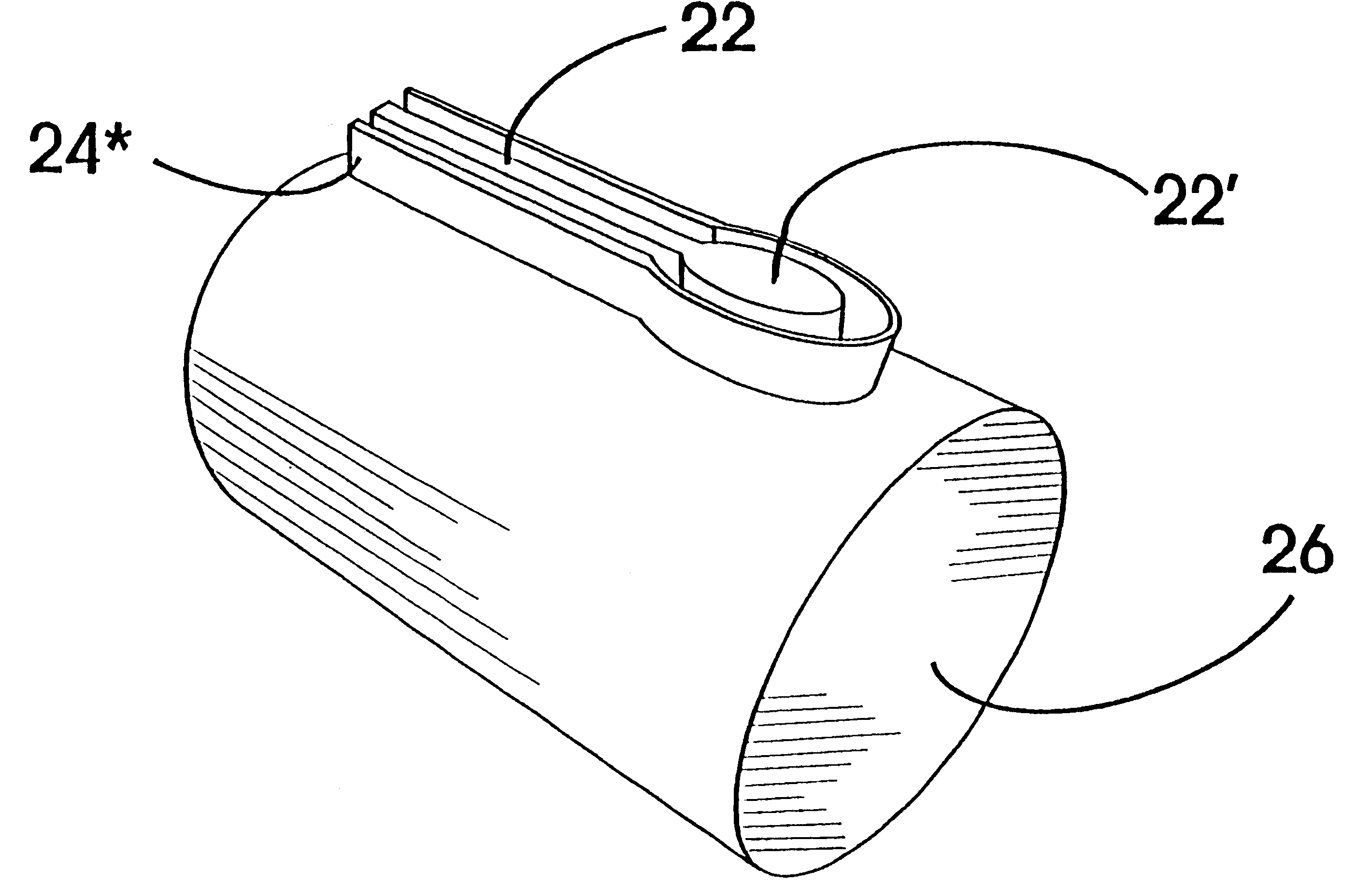
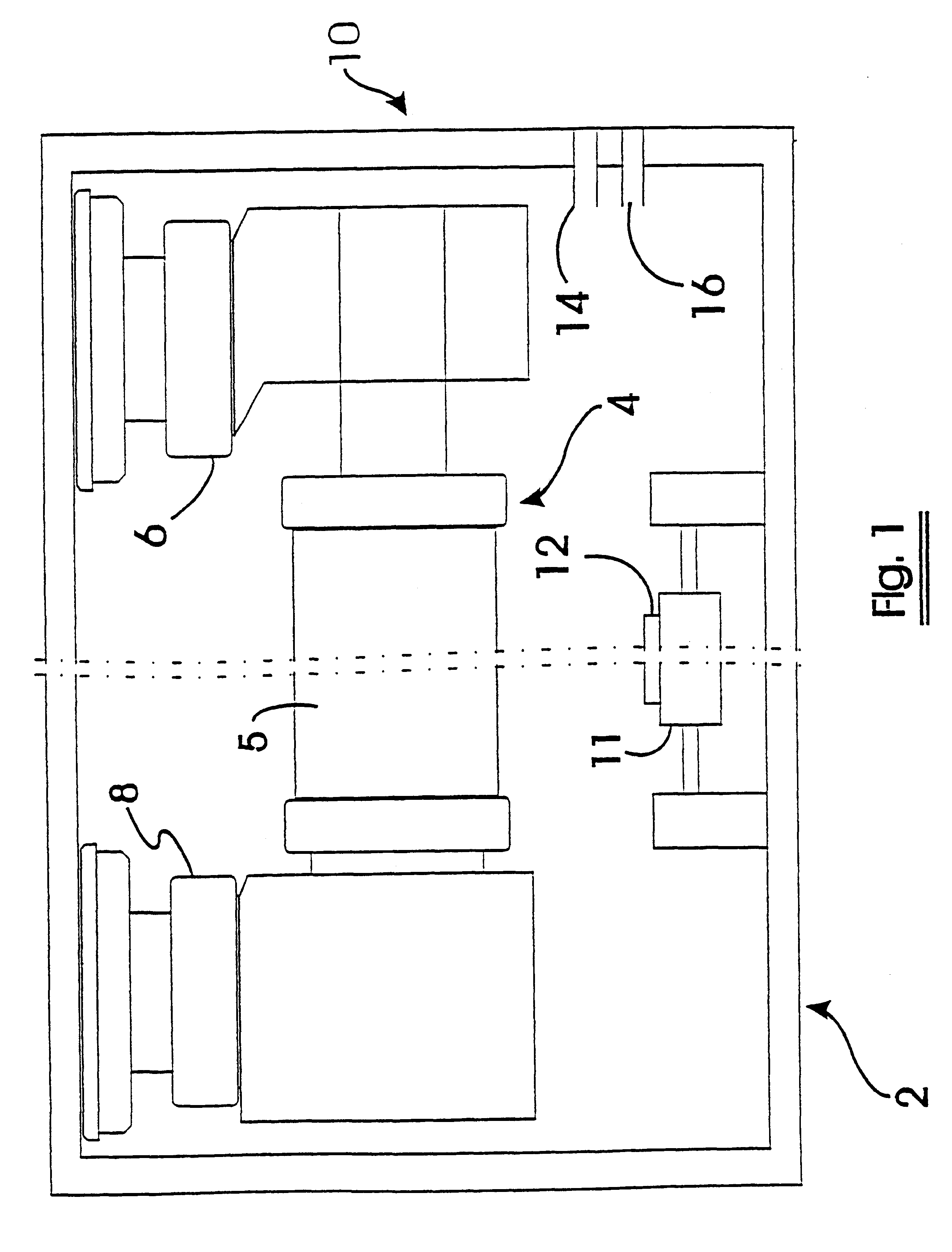
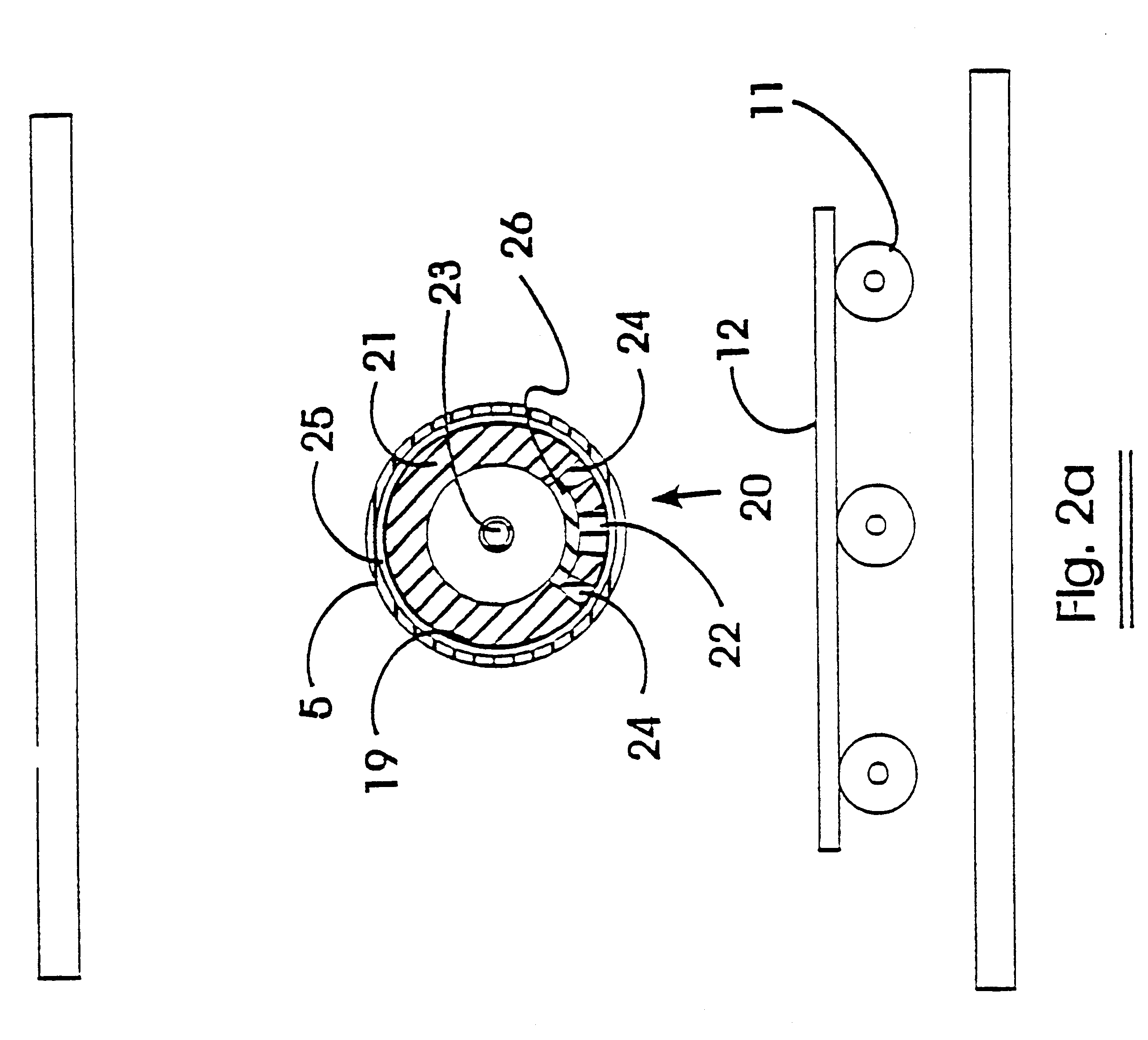
FIGS. 1 and 2a and 2b are schematic views of the sputtering magnetron 10 in accordance with the present invention. FIG. 1 is a schematic side view of the target 4 within the vacuum chamber 2, whereas FIG. 2a is a schematic cross-sectional view through the target 4. FIG. 2b is an enlarged view of a part of the target 4 from FIG. 2a. Vacuum chamber 2 preferably includes a removable, cylindrical rotating target 4. The target 4 may be driven by any suitable drive means, e.g. an electric or hydraulic motor or similar linked to the target 4 through a feed-through 6. The other end of the target 4 may be supported by a further feed-through 8 through which cooling liquid for the target 4 and an electrical supply (not shown) may be brought into chambe...


PUM

PropertyMeasurementUnit
Fractionaaaaaaaaaa
Fractionaaaaaaaaaa
Lengthaaaaaaaaaa

Abstract

A sputtering magnetron with a rotating cylindrical target and a stationary magnet assembly (22, 24*) is described, the magnet assembly (22, 24*) being adapted to produce an elongate plasma race-track on the surface of the target, the elongate race-track having substantially parallel tracks over a substantial portion of its length and being closed at each end by end portions (22'), wherein the spacing between the tracks of the race-track is increased locally to materially effect sputtering onto a substrate. The increase in spacing may be at the end portions or along the parallel track portion. The increase in spacing may provide more even erosion of the target beneath the end portions of the race-track, and provide more even coatings on the substrate.

Description

The present invention relates to an improved rotating cathode magnetron suitable for sputtering or reactive sputtering of materials from a tubular cathode target onto a stationary or moving substrate as well as a method of operating the magnetron. The magnet assembly of the inventive magnetron is arranged in such a way that local variations in the plasma race-track are generated which may provide novel advantages to the sputtering process. In addition, the novel magnet assembly is particularly suitable for curvilinear arrangements.TECHNICAL BACKGROUNDIn standard non-reactive metallic sputter mode, sputtering with planar magnetrons is known. The most important inconvenience is the formation of a groove of erosion in the target material, whereby this groove, and the plasma generating it, are often referred to as a "race track". The non-uniform erosion profile is inherently associated with the magnet configuration below the target. As a consequence, the target has to be replaced just b...

Claims


Application Information

Patent Timeline
IPC IPC(8): H01J37/32H01J37/34C23C14/35
CPCH01J37/3405C23C14/34
Inventor DE BOSSCHER, WILMERTLIEVENS, HUGO
Owner BEKAERT ADVANCED COATINGS
Why Eureka
Try Eureka