
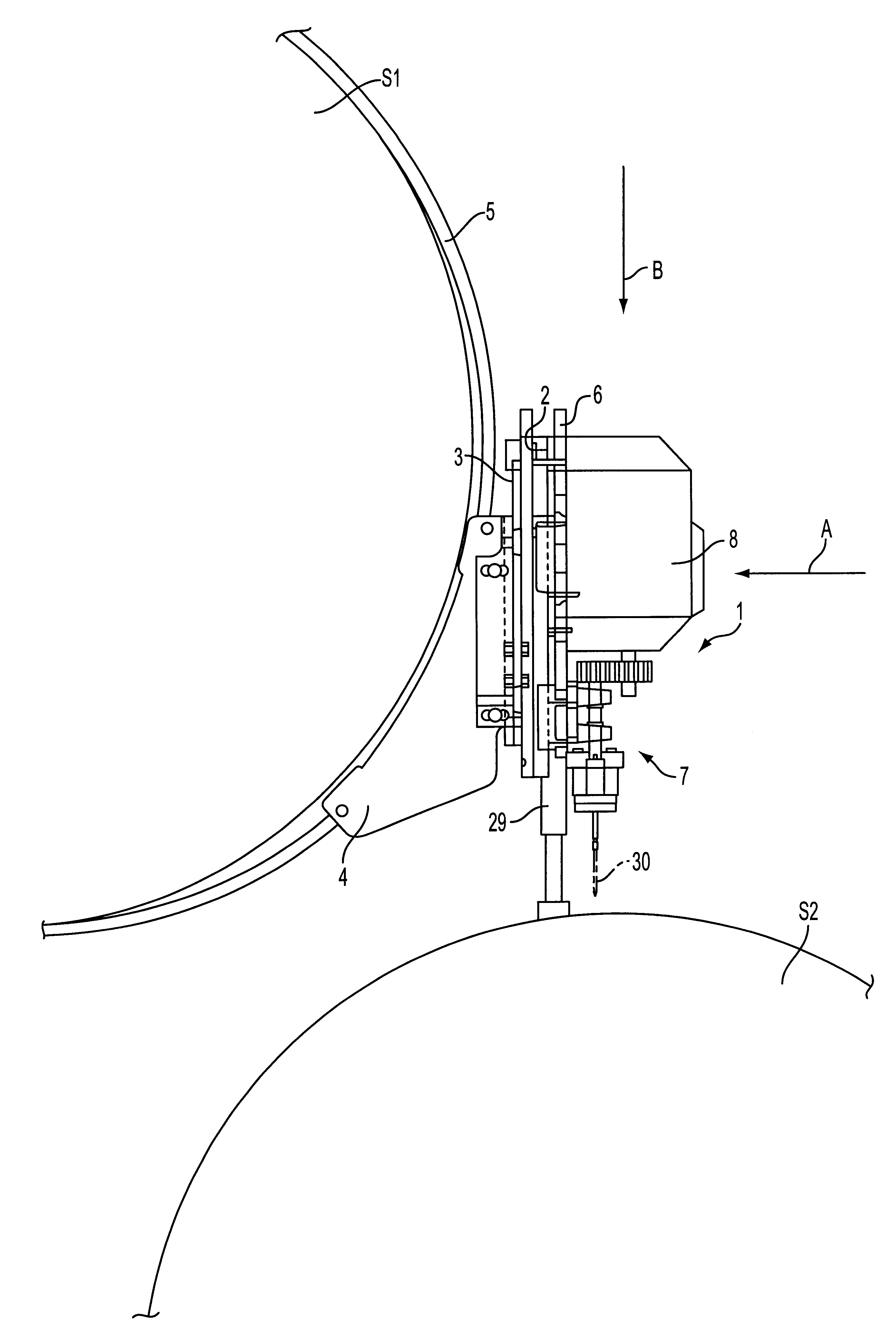
Process and apparatus for drilling holes in the shell of a cylinder

a technology of shell and cylinder, which is applied in the direction of drill jigs, printed circuit manufacture, manufacturing tools, etc., can solve the problems of limited range of spindle head movement and hampered prior art apparatuses

Inactive Publication Date: 2002-03-26
PIKOTEKNIK +1
View PDF20 Cites 12 Cited by
  • Summary
  • Abstract
  • Description
  • Claims
  • Application Information

AI Technical Summary

Benefits of technology

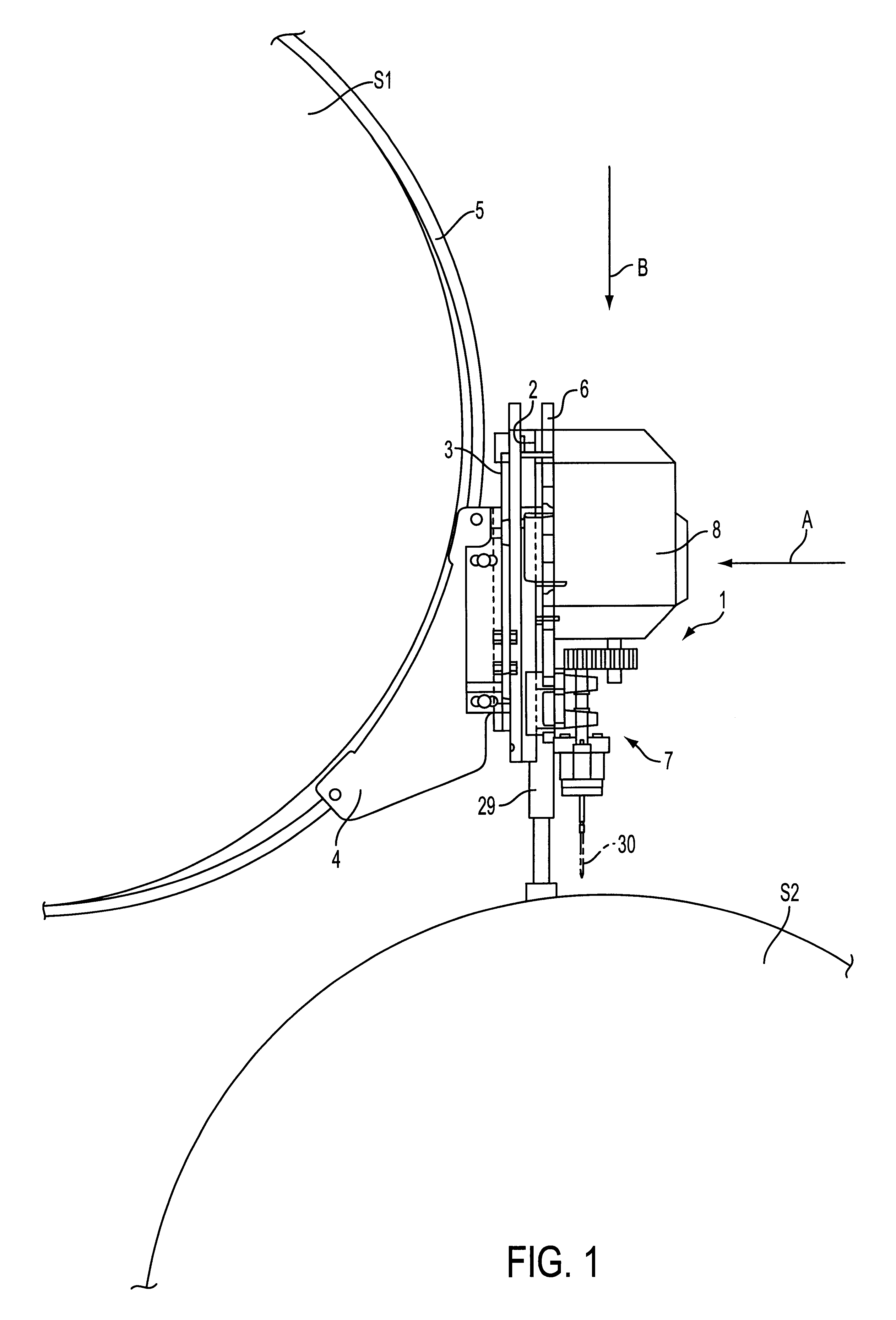
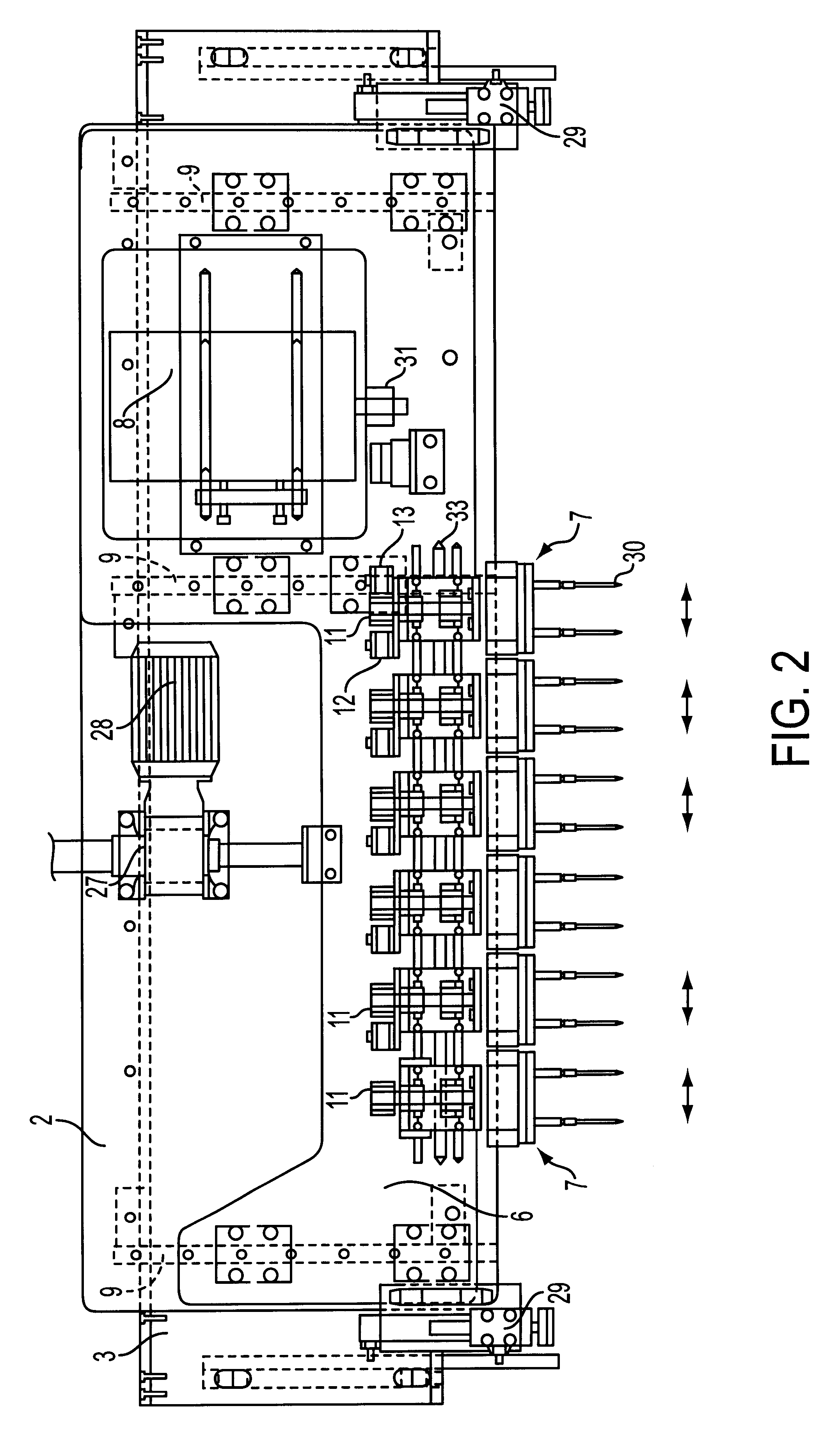
The process and apparatus according to the present invention offer a number of significant benefits. For example, the use of multispindle drilling modules and the positioning of the drilling modules as well as the positioning of the spindle heads within each drilling module via rotation about respective intermediate shafts can provide an extremely wide latitude in the position control of the drilling modules. The position control possibilities may be further extended by using drilling modules adapted to be rotatable about the central drive shaft of the module. Thus, the present invention facilitates drilling without requiring drilling jigs.

Problems solved by technology

These prior art apparatuses are hampered, among other drawbacks, by their complicated construction which results in, e.g., a limited range of spindle head movement.

Method used


Image

  • Process and apparatus for drilling holes in the shell of a cylinder
  • Process and apparatus for drilling holes in the shell of a cylinder
  • Process and apparatus for drilling holes in the shell of a cylinder

Examples


Embodiment Construction

The particulars shown herein are by way of example and for purposes of illustrative discussion of the embodiments of the present invention only and are presented in the cause of providing what is believed to be the most useful and readily understood description of the principles and conceptual aspects of the present invention. In this regard, no attempt is made to show structural details of the present invention in more detail than is necessary for the fundamental understanding of the present invention, the description taken with the drawings making apparent to those skilled in the art how the several forms of the present invention may be embodied in practice.

In the context of the present invention, the term "paper machine" is used for the purposes of explanation and illustration, but it is understood that the present invention can be utilized with other material web producing machines, e.g., a paper machine, a cardboard machine, or a cellulosic web dryer, without departing from the...


PUM

PropertyMeasurementUnit
distanceaaaaaaaaaa
mutual distanceaaaaaaaaaa
tensionaaaaaaaaaa

Abstract

Process and apparatus for operating an apparatus to drill holes in the shell of a paper machine cylinder. The apparatus includes a stationary framework supportable on the paper machine, a feed frame that is radially movable along the stationary framework relative to the shell, and a drive unit. A plurality of drilling modules are coupled to the feed frame, which are rotatable via the drive unit, and the drilling modules include a drive shaft, at least two spindle heads, and at least two intermediate shafts arranged between the drive shaft and the at least two spindle heads, in which at least one of the at least two spindle heads in each drilling module is rotatable about a respective intermediate shaft of the drilling modules. The process includes rotating at least one of the at least two spindle heads about a respective intermediate shaft of the drilling module arranged between a drive shaft and the at least one spindle head, such that a mutual distance between spindle shaft centers of the at least two spindle heads in the drilling modules is adjusted.

Description

The present application claims priority under 35 U.S.C. .sctn.119 of Finnish Patent Application No. 981598, filed on Jul. 13, 1998, the disclosure of which is expressly incorporated by reference herein in its entirety.1. Field of the InventionThe present invention relates to a process for drilling holes in the shell of a cylinder such as a paper machine cylinder, without requiring removal of the cylinder from its operating position. The process utilizes a multispindle drilling apparatus including a device for controlling a distance between drill centers of adjacent drilling modules.The present invention also relates to an apparatus for drilling holes in the shell of paper machine cylinder. The apparatus includes a stationary framework supportable on the paper machine and a feed frame movable along the stationary framework radially toward the shell of the cylinder. The feed frame is coupled to a plurality of drilling modules that are adapted for rotation via a drive unit.2. Discussio...

Claims


Application Information

Patent Timeline
Patent Type & Authority Patents(United States)
IPC IPC(8): B23B39/00B23B39/16
CPCB23B39/162B23B39/167Y10T408/3839Y10T408/3811Y10T408/385Y10T408/03
Inventor VESTERLUND, INGMARKUGLER, GEORGOECHSLE, MARKUSKAHL, PETER
Owner PIKOTEKNIK
Learn More