
Arrangement for use in an antenna array for transmitting and receiving at at least one frequency in at least two polarizations

Inactive Publication Date: 2002-02-26
TELETON LM ERICSSON
View PDF11 Cites 26 Cited by
  • Summary
  • Abstract
  • Description
  • Claims
  • Application Information

AI Technical Summary

Benefits of technology

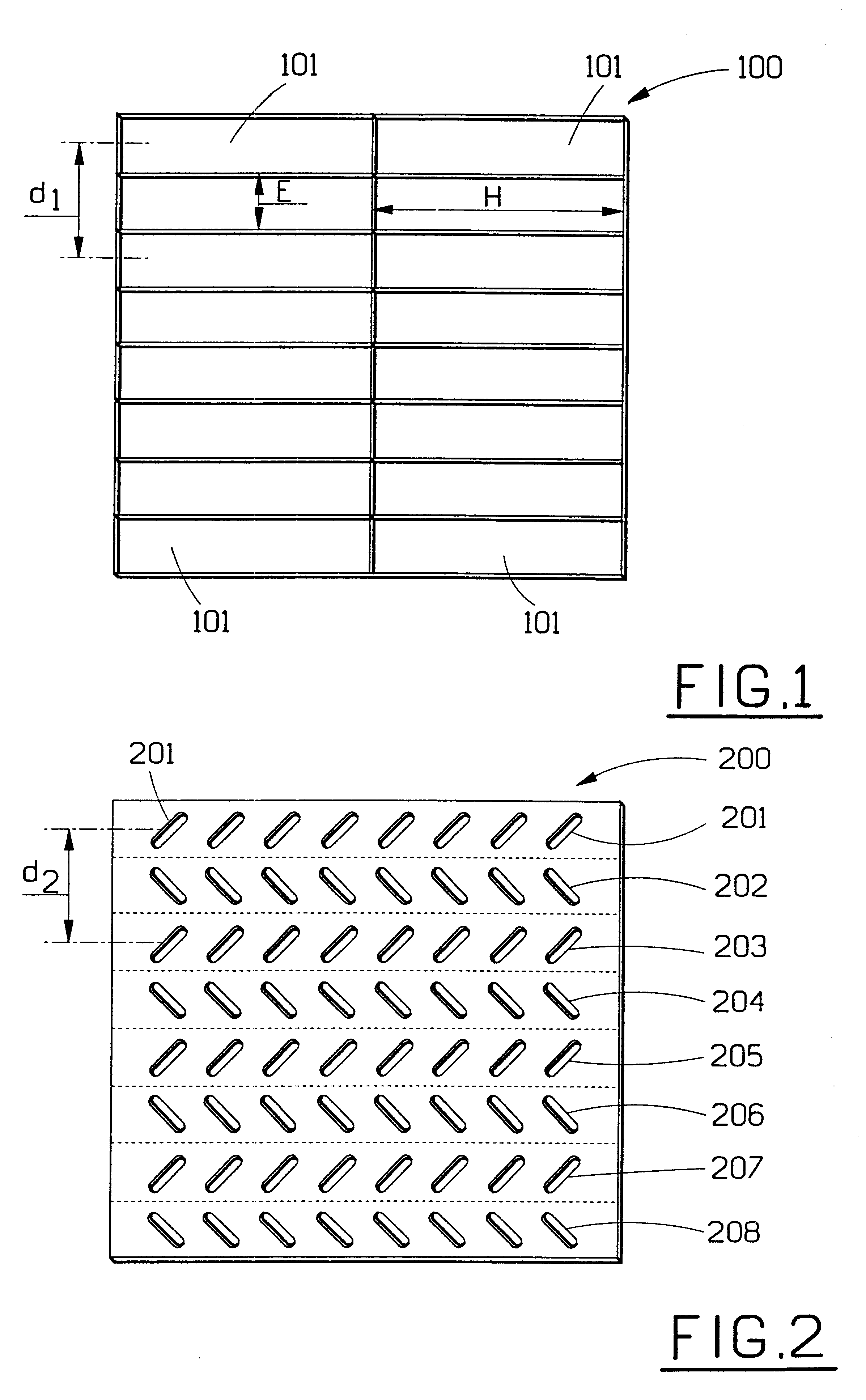
According to the invention, the waveguides can be constructed with dimensions which allow one row of waveguides intended for the one polarization to be placed between two rows of waveguides intended for the second polarization at the same time as the distance between two rows of waveguides intended for the same polarization is such that the level of the grating lobes is low or negligible. Furthermore, according to the invention, the antenna element s in one and the same row can be placed closer to one another than otherwise, which also contributes to the avoidance of grating lobes.
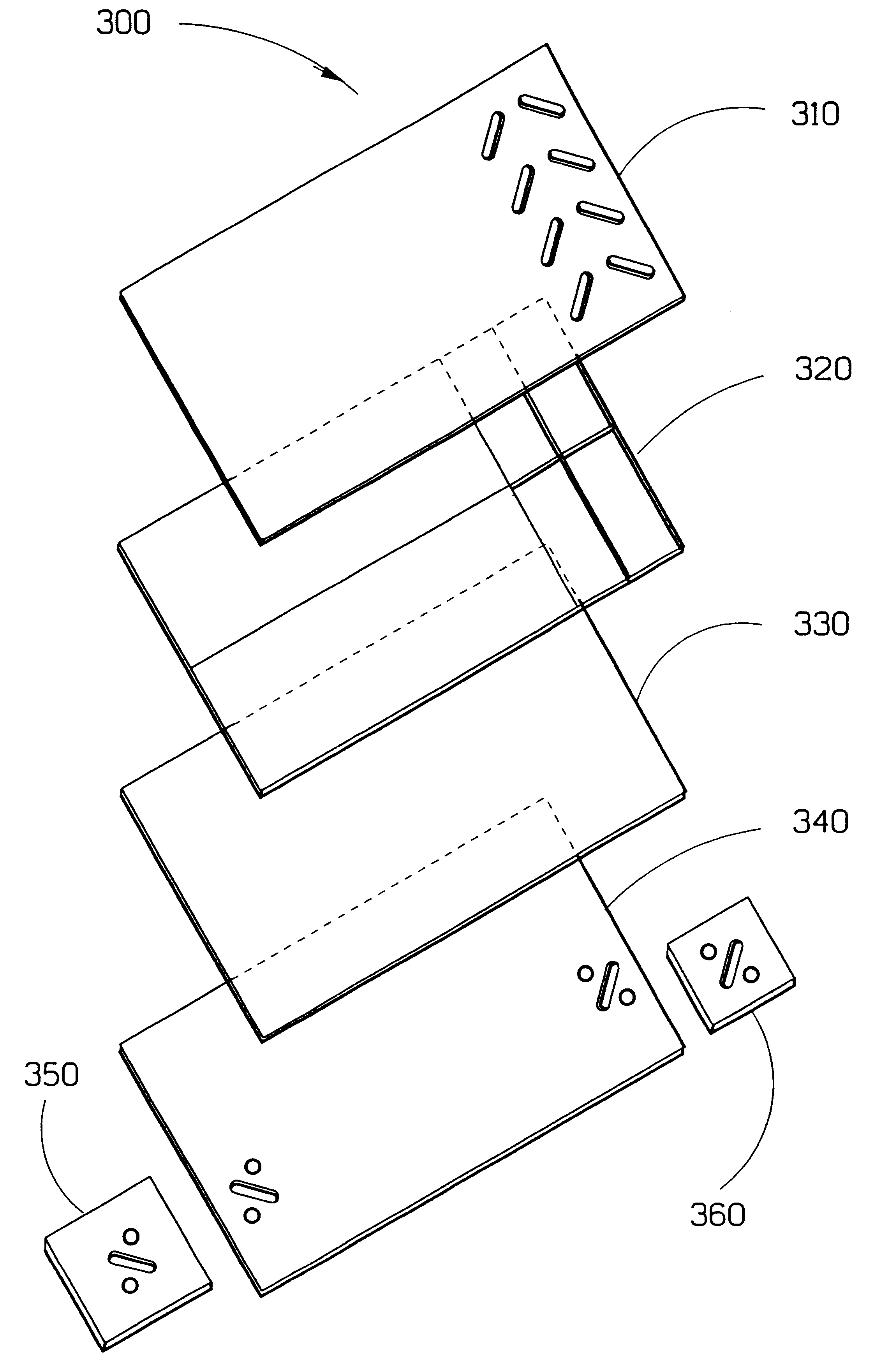
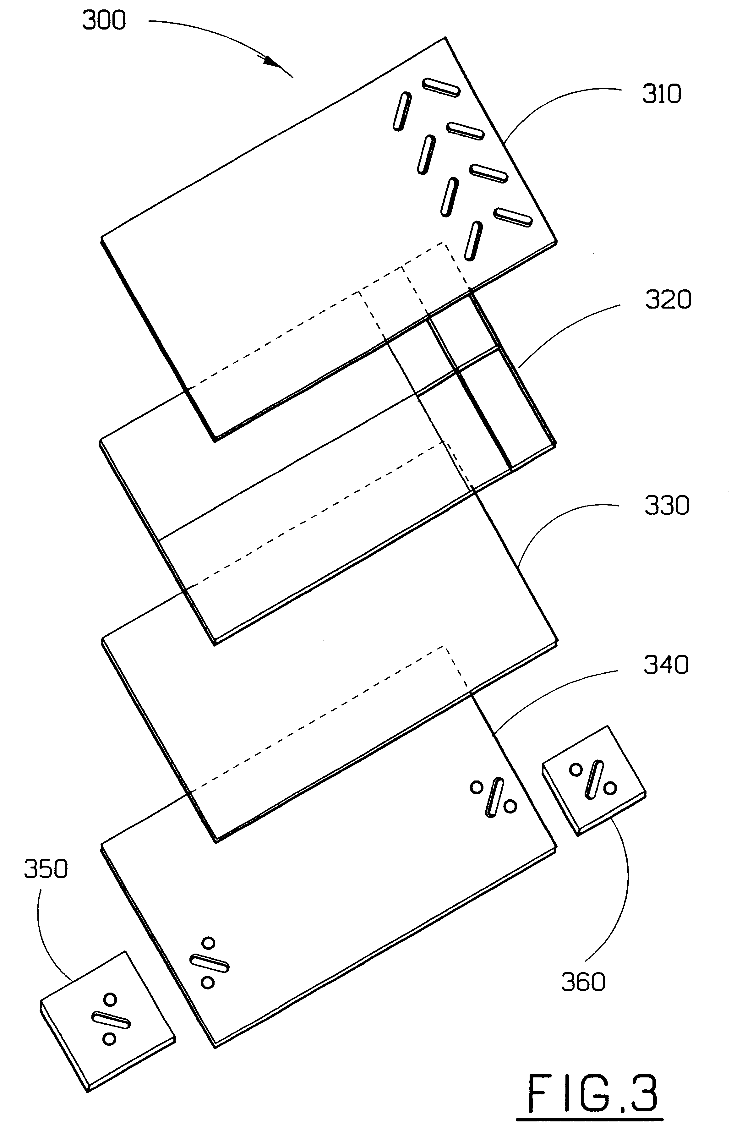
The antenna elements can be suitably arranged in a first separate plate which has its major extension in a first and a second plane of extension. The first plate is arranged on the feeding structure which also includes at least one second separate plate which has its major extension in a first and a second plane of extension. In the second plate, a number of continuous recesses are arranged which are constructed to function as waveguides at the said at least one frequency. This plate structure makes the arrangement simple and inexpensive to produce.
The invention thus provides a capability of creating a compact single-frequency or multi-frequency dual-polarized antenna array which has small or negligible grating lobes. An antenna array with an arrangement according to the invention can also be produced at low cost.
The invention also provides the capability of constructing an arrangement for use in an antenna array for transmitting and receiving at at least two frequencies in one polarization, comprising at least two antenna elements, where each antenna element is intended for one of the at least two frequencies, the antenna elements being arranged on a feeding structure which conducts electrical signals to and from the antenna elements, and where the feeding structure comprises a number of waveguides dimensioned for the said at least two frequencies, whereby different waveguides are used for feeding the antenna elements intended for different frequencies, and the waveguides are completely or partially filled with a material, the dielectric constant of which is higher than that of air, whereby an alternative antenna array with small or negligible grating lobes can be obtained.

Problems solved by technology

This provides a relatively good operation but is a space-consuming solution.
However, reflector antennas, too, are a space-consuming solution.
However, known dual-polarized antennas in microstrip technology give relatively high losses.

Method used


Image

  • Arrangement for use in an antenna array for transmitting and receiving at at least one frequency in at least two polarizations
  • Arrangement for use in an antenna array for transmitting and receiving at at least one frequency in at least two polarizations
  • Arrangement for use in an antenna array for transmitting and receiving at at least one frequency in at least two polarizations

Examples


Embodiment Construction

The problem which is solved by the present invention is thus to be able to make a dual-polarized antenna array which is small and compact, inexpensive to produce and has small or negligible grating lobes.

This problem is solved with the aid of an arrangement for use in an antenna array for transmitting and receiving at at least one frequency in at least one first and one second polarization, which comprises at least two antenna elements, where each antenna element is intended for one of the two polarizations, with the antenna elements being arranged in a feeding structure which conducts electrical signals to and from the antenna elements. The feeding structure comprises a number of waveguides dimensioned for the said at least one frequency, and different waveguides are used for feeding antenna elements intended for different polarization. According to the invention, the waveguides are completely or partially filled with a material, the dielectric constant of which is higher than that...


PUM


Abstract

The invention provides an arrangement for use in an antenna array for transmitting and receiving at at least one frequency in at least two polarizations, comprising at least two antenna elements (210-208), where each antenna element is intended for one of the two polarizations, the antenna elements being arranged on a feeding structure (100, 320, 420) which conducts electrical signals to and from the antenna elements (201-208). The invention is characterized in that the feeding structure (100, 320, 420) comprises a number of waveguides (101) dimensioned for the said at least one frequency, in that the different waveguides are used for feeding the antenna elements (201-208) intended for different polarization, and in that the waveguides (101) are completely or partially filled with a material, the dielectric constant of which is higher than that of air, whereby an antenna array with small or negligible grating lobes can be obtained.The antenna elements (201-208) and the feeding structure (100, 320) are suitably arranged each on a separate plate (200, 310, 410) and in the feeding plate (100, 320, 420), a number of continuous recesses (101) are arranged which are constructed to operate as waveguides at the said at least one frequency.

Description

The present invention provides an arrangement which is intended to be used in an antenna array for transmitting and receiving at at least one frequency in at least two polarizations preferably in the microwave range.The arrangement comprises a plate with antenna elements, where the antenna elements are fed by waveguides in an underlying plate which is part of a feeding structure. The specific construction according to the invention of the feeding structure provides a possibility of placing rows of antenna elements intended for a first polarization between rows of antenna elements intended for a second polarization whilst keeping the grating lobes of the antenna at a low level.1. Prior ArtWhen transmitting electromagnetic signals in a system in, for example, the microwave range, it is very desirable that the antennas which are used in the system should be as small and compact as possible and, at the same time, provide a system in which they are included with the highest possible tran...

Claims


Application Information

Patent Timeline
IPC IPC(8): H01Q1/24H01Q25/04H01Q21/00H01Q25/00H01Q21/24
CPCH01Q1/246H01Q21/0037H01Q25/04H01Q21/24H01Q21/005
Inventor SNYGG, GORANJOHANSSON, SUNESVENSSON, BENGT
Owner TELETON LM ERICSSON
Learn More