
Process and apparatus for the production of a deodorant or antiperspirant composition

a technology of antiperspirant and composition, applied in the field of deodorant or antiperspirant sticks, can solve the problems of increasing the overall energy consumption of the process, affecting the incorporation of heat-sensitive constituents, and needing to mask rancid odours

Inactive Publication Date: 2002-01-15
UNILEVER HOME & PERSONAL CARE USA DIV OF CONOPCO IN C
View PDF12 Cites 62 Cited by
  • Summary
  • Abstract
  • Description
  • Claims
  • Application Information

AI Technical Summary

Benefits of technology

It is a particular advantage in many aspects of the present invention that the deodorant or antiperspirant composition is able to enter the container or mould at a lower temperature than in a simple casting technique. When heating amounts of solid deodorant or antiperspirant compositions continuously at the rate dictated by the rate at which it is continuous dispensed, less heat losses can arise. Moreover it is quicker and easier to control the temperature of the composition during its production and delivery compared with inside the container or mould. For that reason, less energy overall may be required, and also because the operating temperatures can be lower. The present invention therefore offers economy in operation.

Problems solved by technology

There are several disadvantages associated with preparing a large volume of molten deodorant or antiperspirant composition for batch processing.
During this period, heat is dissipated, thereby increasing the overall energy consumption for the process.
Secondly, the maintenance of a relatively high temperature needed to keep the composition molten for an extended period can not only cause the degradation of some common constituents, such as the oxidation of waxes or fats, resulting potentially in rancid odours that need to be masked by additional perfume, but also constrains the incorporation of heat sensitive constituents, such as any perfume itself, on account of the likelihood that they will be impaired before the sticks are formed.
In addition, the conventional batch process is poorly suited to switching between different formulations in view of the time taken to cleanse the apparatus between batch preparations to avoid cross contamination.
One major problem associated with a casting process for deodorant or antiperspirant compositions is that they tend to shrink within the stick barrels as they cool.
This is highly undesirable because shrinkage can adversely affect the visual appearance of the stick.
This problem becomes apparent particularly when the stick barrels are filled from the top.
On the other hand, bottom filling of stick barrels is often more wasteful of material.
A second major problem arises because the composition must be kept mobile whilst it is being fed from its production / storage vessel to the filling station so as to avoid line blockage which would be extremely disruptive to production.
Segregation is inherently undesirable for users of the stick, because its performance can vary depending on how much of the stick has been consumed.
Whilst this modification may alleviate the formation of agglomerates of actives, it does not address various other aspects of a batch / pour mould method as indicated above.
This is of limited value to manufacturers of antiperspirant compositions in that the process is not applicable to any antiperspirant material having a surface area of below 2m.sup.2 / g, and introduces an extra step into the manufacturing process, namely determining the surface area for all batches of material that are contemplated for use.
Moreover, it does not address various other aspects of a batch / pour mould method as indicated above.
Such apparatus and methods do not provide teaching that is directly applicable to deodorant or antiperspirant compositions, due to very different structuring mechanisms.
Such a combination of conditions is not applicable to the satisfactory injection moulding of deodorant or antiperspirant compositions.
Such a process also reduces the extent of heat to be removed from the container or mould before the stick solidifies and affects the crystalline structure of the stick.
The structure of the composition is impaired if it is injected at too low a temperature.
Employment of a smaller temperature difference increases the risk of line blockage between the screw extruder and the cast nozzle, for example to or from a holder tank typically deployed above the filling station to permit the fluid formulation to flow under gravity into the barrel or other container.
Some deodorant or antiperspirant compositions can demonstrate undesirable aesthetic properties if they are injection moulded under the wrong conditions, and particularly when moulded at a temperature that is too low and a pressure that is excessive.
That is to say, some deodorant or antiperspirant compositions which are solid when moulded under the correct conditions have a complex structure which can be disrupted if the solid is exposed to excessive shearing stresses during injection.
The structure of the composition may not be re-established after such shearing, so that the deodorant or antiperspirant composition would remain in a soft or otherwise undesirable state.
On the other hand, reciprocating extruders can have an increased tendency to introduce gas (air) into antiperspirant or deodorant formulation during processing, which can impair the finish and homogeneity of the final stick.
There are particular problems with conveying fluid deodorant or antiperspirant composition.
It has been found that there can be a problem in simple filling with jetting or "snaking" of the material in the container or mould.
Rotation of the heads about the axis of the container / mould can result in a swirl / stripe effect.

Method used


Image

  • Process and apparatus for the production of a deodorant or antiperspirant composition
  • Process and apparatus for the production of a deodorant or antiperspirant composition
  • Process and apparatus for the production of a deodorant or antiperspirant composition

Examples


example 1

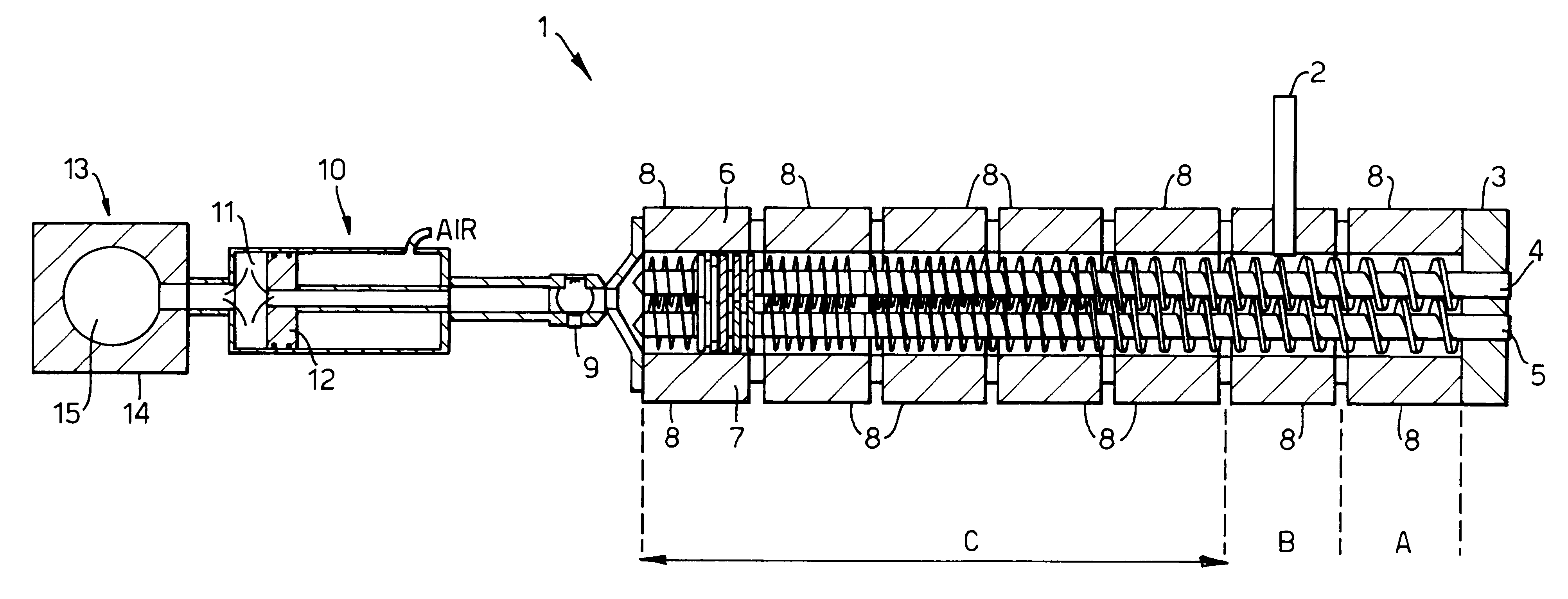
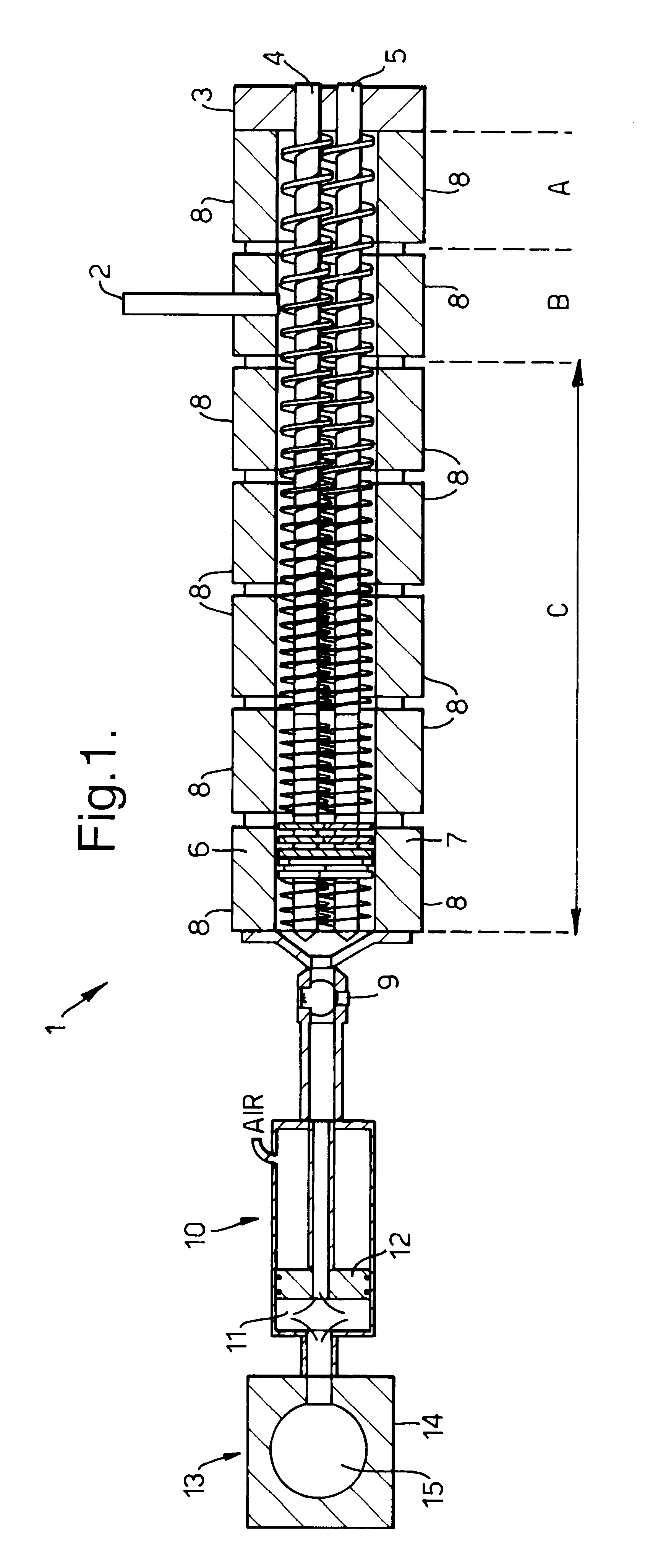
In Example 1, antiperspirant sticks of Formulation A summarised below were prepared employing apparatus according to FIG. 1, a Betol co-rotating twin screw extruder, having 40 mm diameter screws and eight temperature control zones leading via a connection valve to piston-type injection unit in which the connection valve and injection head were also temperature controlled. In this example, the extruder acted to transport the fluid antiperspirant composition to the injection unit.

A batch of a composition within Formulation A was prepared in conventional equipment to produce a solid mass and subsequently melted in a conventional stirred heating jacketed vessel. It was maintained at a temperature of approximately 60 to 65.degree. C. and fed in the form of a fluid mass via a metering pump into the Betol extruder. Zone A was controlled to about 30.degree. C., in order to generate a solid block of material to minimise loss of the composition. In zone B of the extruder, the temperature was ...

example 2

In this Example, apparatus in accordance with FIG. 1 and substantially as described in Example 1, except that the twin screws each had a diameter of 30 mm, was employed to produce sticks from a composition within Formulation B. Formulation B was the same as Formulation A, except that the antiperspirant active was an Al-Zr antiperspirant active which had a larger average particle size than the active in Formulation A, and which was more prone to sedimentation.

The composition was injected into the barrels at a temperature selected in the range of 44 to 48.5.degree. C. The products after they had cooled to ambient temperature were assessed as to their surface appearance, hardness and sedimentation of active. It was found that the sticks having the best properties were those which were injected at a temperature of from 46 to 48.5.degree. C., compared with a regular set temperature of about 49.degree. C., in that they exhibited acceptable resistance to sedimentation and showed good surfa...

example 3

In this Example, a composition within Formulation C as shown below was in-line compounded and injected into either barrels or moulds to form sticks using the process described below.

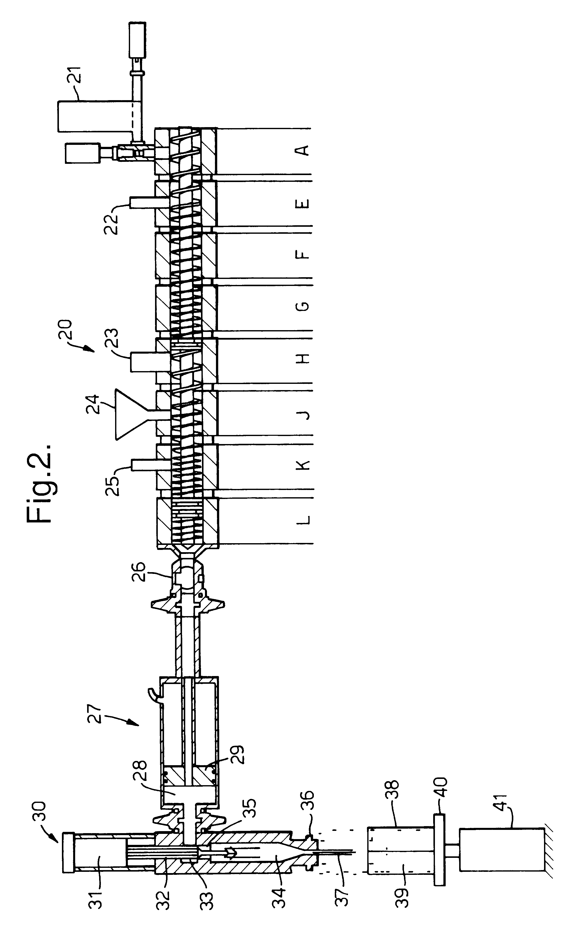
In this Example, sticks were made employing apparatus according to FIG. 2 and comprising a Werner & Pfleiderer co-rotating twin screw extruder having a plurality of temperature control zones, feeding an injection moulding apparatus having a low shear in-line injection head. The extruder had 30 mm diameter screws rotating at rates controlled within the range 30 to 200 rpm. In this Example, the extruder acted not only to transport the composition to the injection unit, but also as a continuous in-line compounder.

The composition within Formulation C above was compounded by feeding the constituents into the screw extruder in the following order:

The waxes were introduced via a volume feeder into zone A, then the silicone fluid and the emollient oil were pumped in via metered pumps into zone E. Zone A was main...


PUM

PropertyMeasurementUnit
Temperatureaaaaaaaaaa
Pressureaaaaaaaaaa
Pressureaaaaaaaaaa

Abstract

In a first aspect, a process for forming deodorant or antiperspirant sticks by continuously forming a mobile composition for dispensing into containers or molds at a rate matched with the rate at which it is dispensed, and in other aspects a process in which a mobile deodorant or antiperspirant composition is dispensed by injection molding, i.e. a process in which the deodorant or antiperspirant composition is dispensed under pressure. The composition at the time of injection moulding is preferably either in the vicinity of its regular set temperature, particularly in the range of about 0-3° C. below the regular set temperature and / or partially structured at the time of its delivery it into a container or mold. The deodorant or antiperspirant composition is preferably continuously produced in a screw extruder, especially a twin screw extruder, which is controlled to deliver the composition in a substantially semi-solid state, at a temperature close to its regular set temperature and is injected into the container or barrel at a pressure at the point of injection that is often greater than 15 psi. and in many instances from 200 to 400 psi in the injection head. Apparatus for forming deodorant or antiperspirant sticks by injection molding is also described. The combined process offers benefits for incorporating sensitive ingredients and ameliorating sedimentation of particulates such as particulate antiperspirant actives.

Description

The present invention relates to a process and apparatus for forming a deodorant or antiperspirant composition, and particularly to compositions suitable for forming into sticks, to a process and apparatus for forming such sticks and to such sticks obtained thereby.BACKGROUND AND PRIOR ARTDeodorant or antiperspirant sticks are conventionally manufactured by casting. In conventional casting processes, the constituents of a deodorant or antiperspirant stick composition are mixed in a large vessel, and heated to form a molten composition. Whilst the composition is in a mobile and readily pourable state, it is poured into the its container of the desired shape, which is sometimes called a barrel, and sometimes called a canister. Hereinafter, reference to a barrel includes reference to a canister. The composition is thereafter cooled until it solidifies. The barrel is either capped or bottomed, depending on whether bottom fill or top fill has been employed. If the barrel has been bottom ...

Claims


Application Information

Patent Timeline
IPC IPC(8): A45D40/00A45D40/16
CPCA45D40/16B29C2045/466
Inventor ALLAN, PETER STEWARTBIBBY, ELAINE SUSANNEBROWNE, MICHAEL ANDREWLANGEVELD, ELFRIEDE MARIALLOYD, PAULMANLEY, REGINALDOWEN, ROBERT JRENNIE, PAUL RIESSENSCOTT, JEAN LESLEYSTOCKER, FREDERICK EDMUNDTARVERDI, KARNIKTHORPE, JACQUELINE MARIA
Owner UNILEVER HOME & PERSONAL CARE USA DIV OF CONOPCO IN C
Learn More