Vent valve assembly

a technology of positive sealing and valve assembly, which is applied in the direction of mechanical equipment, transportation and packaging, and functional valve types, etc., can solve the problems of fuel vapor escape, psi valves that reduce, but not eliminate, and previously known psi valves that have proven inadequate to meet government standards, and achieve the effect of improving the fluid seal

Inactive Publication Date: 2002-01-15
MARTINREA IND INC
View PDF3 Cites 17 Cited by
  • Summary
  • Abstract
  • Description
  • Claims
  • Application Information

AI Technical Summary

Benefits of technology

Since the entire exterior of the housing is continuous between the fluid seal between the housing and the fill tube and the end of the housing at which the flapper valve is mounted, the escape of fuel vapors from the fuel tank around the exterior of the housing is substantially precluded. Furthermore, in order to enhance the fluid seal between the flapper valve and the housing wall, a fluid seal is preferably disposed around the outer periphery of the PSI valve and this fluid seal engages the housing wall when the flapper valve is rotated to its assembled position.

Problems solved by technology

These previously known PSI valves, however, have been rather rudimentary in design.
As such, these previously known PSI valves reduce, but do not eliminate, the escape of fuel vapors from the fuel tank through the fill tube.
However, in view of ever increasing governmental regulations regarding the emissions of fuel vapors into the atmosphere, these previously known PSI valves have proven inadequate to meet government standards.
One reason that these previously known PSI valves have been unable to meet government standards is that the PSI valve is secured to the fill tube by fasteners extending through the fill tube.
A still further disadvantage of these previously known PSI valves is that the attachment of the PSI valve to the fill tube was labor intensive and oftentimes required special tools.
As such, these additional labor costs increased the overall cost of the PSI valve assembly.

Method used


Image

  • Vent valve assembly
  • Vent valve assembly
  • Vent valve assembly

Examples


Embodiment Construction

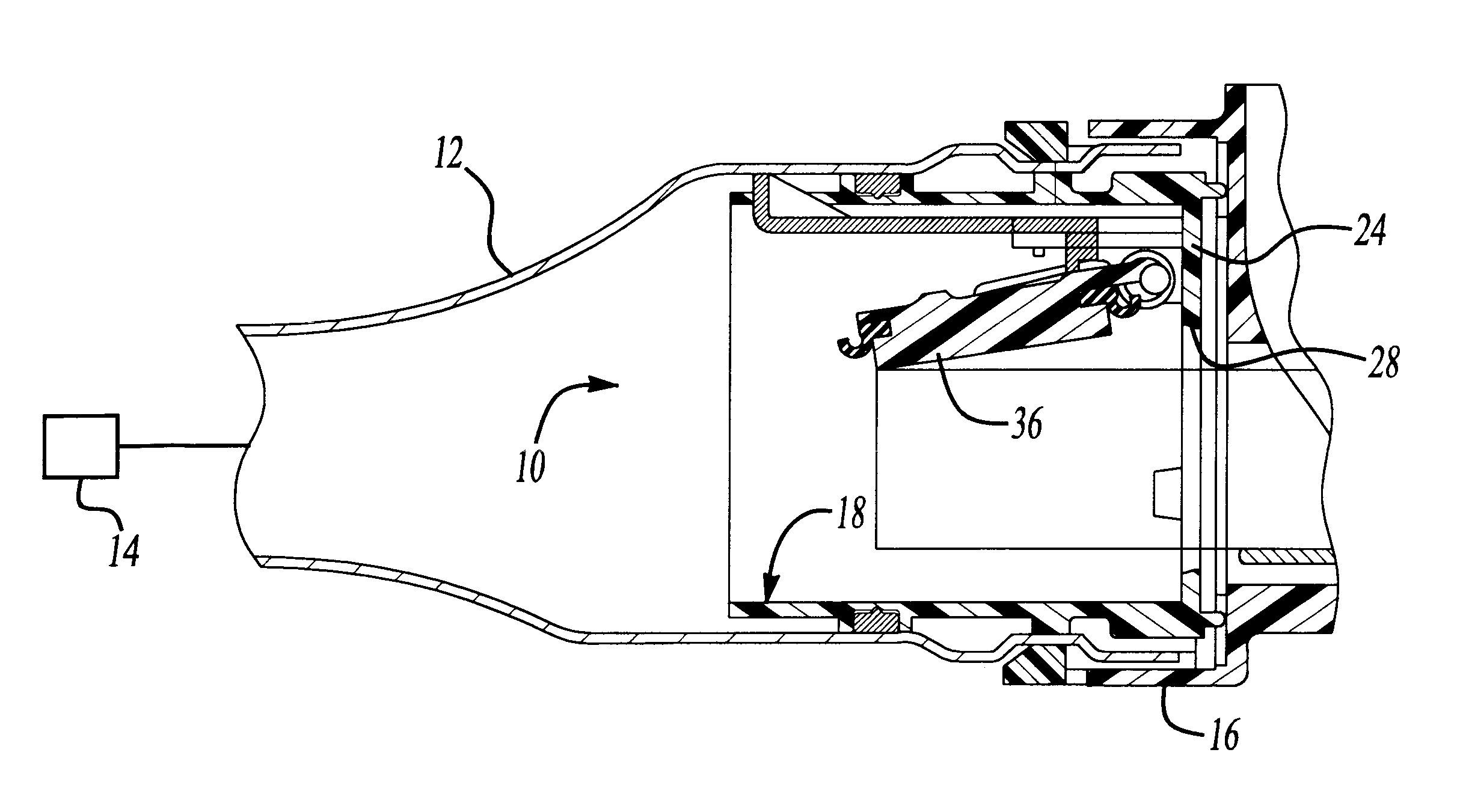
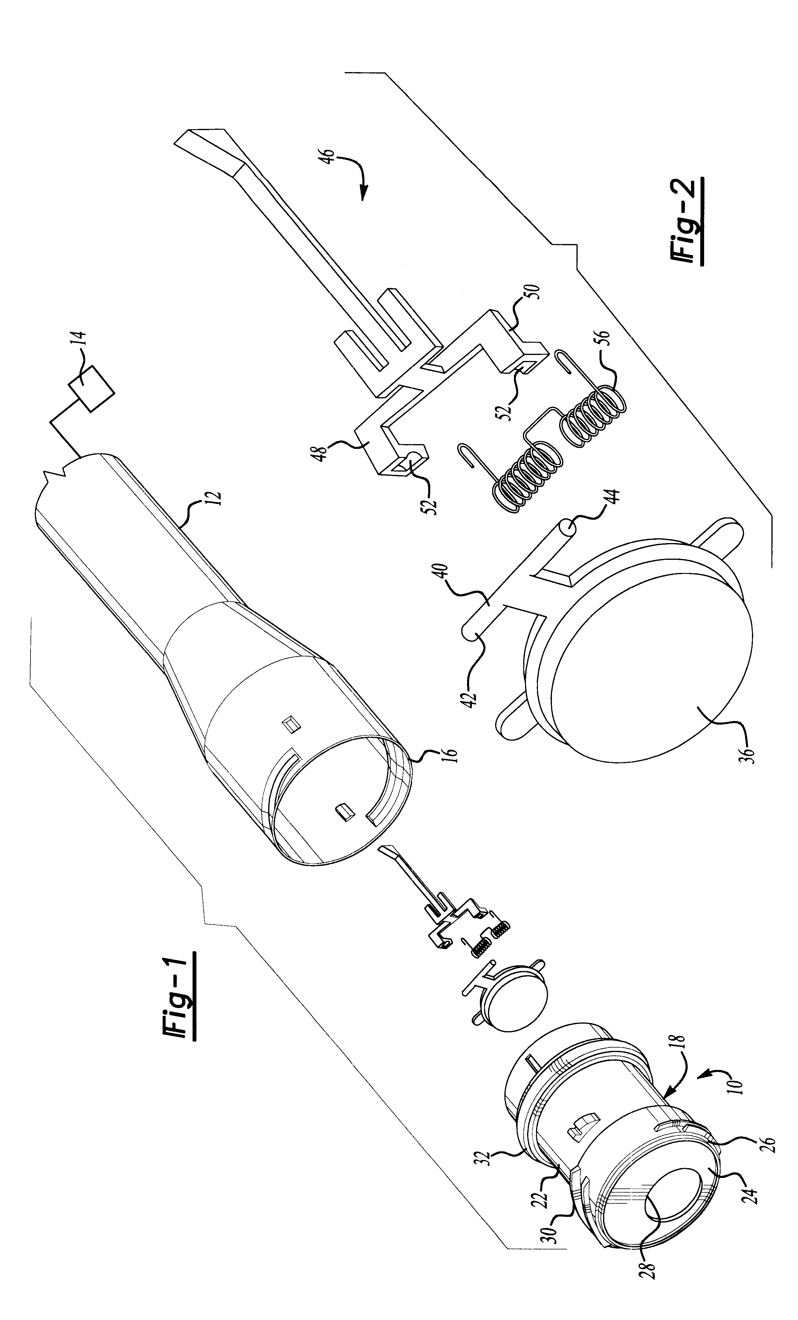
With reference first to FIGS. 1, 6 and 6A, a preferred embodiment of the PSI valve assembly 10 of the present invention is there shown for use with an automotive vehicle having a fuel fill tube 12 open at one end to a fuel tank 14 (illustrated diagrammatically). The fill tube 12 is generally tubular and cylindrical in shape and is open at its end 16 opposite from the fuel tank 14.

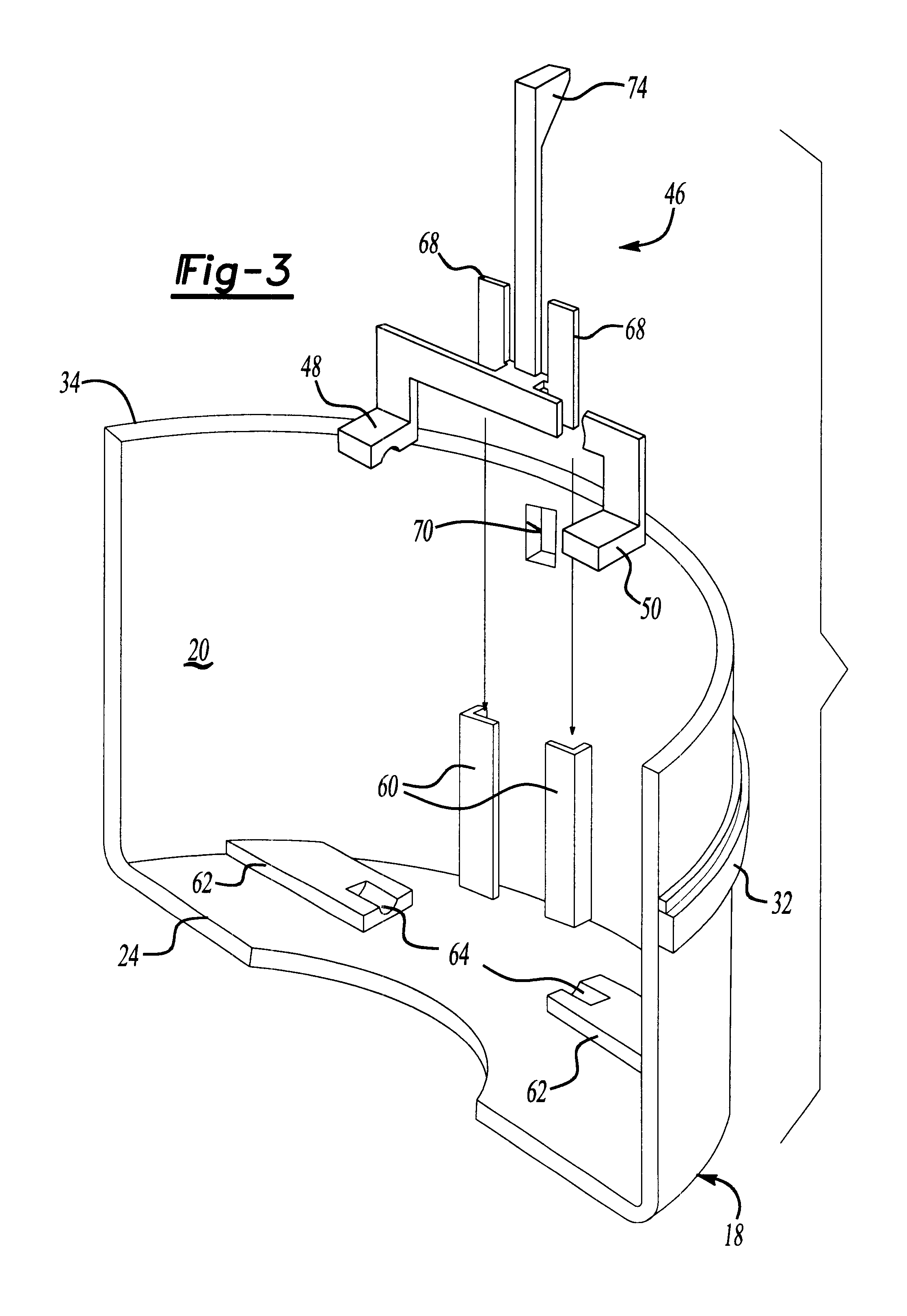
The PSI valve assembly 10 comprises a tubular and cylindrical housing 18 having both an interior 20 and an exterior 22. A wall 24 extends across the interior 20 of the housing 18 adjacent one end 26 of the housing 18. A circular through opening 28 is provided through the housing wall 24. Additionally, preferably the housing 18 as well as the wall 24 are of a one-piece plastic construction.

With reference now particularly to FIG. 6, the housing 18 is coaxially mounted within the interior of the fill tube 12 such that the housing 18 is mounted fluidly in series with the fill tube 12. Additionally, with the hou...


PUM


Abstract

A positive sealing inlet (PSI) valve assembly is provided for an automotive fuel tank fill tube. The PSI valve assembly includes a tubular housing having an interior and an exterior and this housing is fluidly mounted in series with the fuel tank fill tube. The housing includes a wall extending across the interior of the housing adjacent one end and this wall includes a through opening. A flapper valve is movable between an open and a closed position. In its closed position, the flapper valve overlies and closes the wall opening. Conversely, in its open position, the flapper valve is positioned away from the wall opening to permit nozzle insertion through the wall opening. The PSI valve is pivotally connected to a valve holder and this valve holder is mounted entirely within the interior of the housing. A spring is operatively disposed between the valve holder and flapper valve and urges the vent valve towards its closed position.

Description

I. Field of the InventionThe present invention relates to a positive sealing inlet (PSI) valve assembly for the fill tube on the fuel tank of an automotive vehicle.II. Description of the Prior ArtIn previously known automotive vehicles, a fill tube is provided between the exterior of the automotive vehicle and the fuel tank. While in many previously known automotive vehicles, the fill tube is merely covered by a removable fill cap, in other types of previously known automotive vehicles, a PSI valve is provided across the fill tube. This PSI valve is designed to minimize the escape of fuel vapors from the fuel tank through the fill tube.These previously known PSI valves, however, have been rather rudimentary in design. As such, these previously known PSI valves reduce, but do not eliminate, the escape of fuel vapors from the fuel tank through the fill tube. However, in view of ever increasing governmental regulations regarding the emissions of fuel vapors into the atmosphere, these p...

Claims


Application Information

Patent Timeline
Patent Type & Authority Patents(United States)
IPC IPC(8): F16K15/02F16K15/03B60K15/04
CPCF16K15/033Y10T137/86332Y10T137/86372Y10T137/86324B60K15/04
Inventor GABBEY, DAVID JOHNCUNKLE, DANIEL PAUL
Owner MARTINREA IND INC
Why Eureka
Try Eureka