
Method of filling a receptacle

Inactive Publication Date: 2002-01-01
SERAC GROUP
View PDF5 Cites 20 Cited by
  • Summary
  • Abstract
  • Description
  • Claims
  • Application Information

AI Technical Summary

Benefits of technology

An object of the present invention is to propose a method of filling a receptacle that can be implemented with algorithms that are simple, while nevertheless making it possible to obtain high accuracy concerning the net weight of the substance introduced into the receptacle.
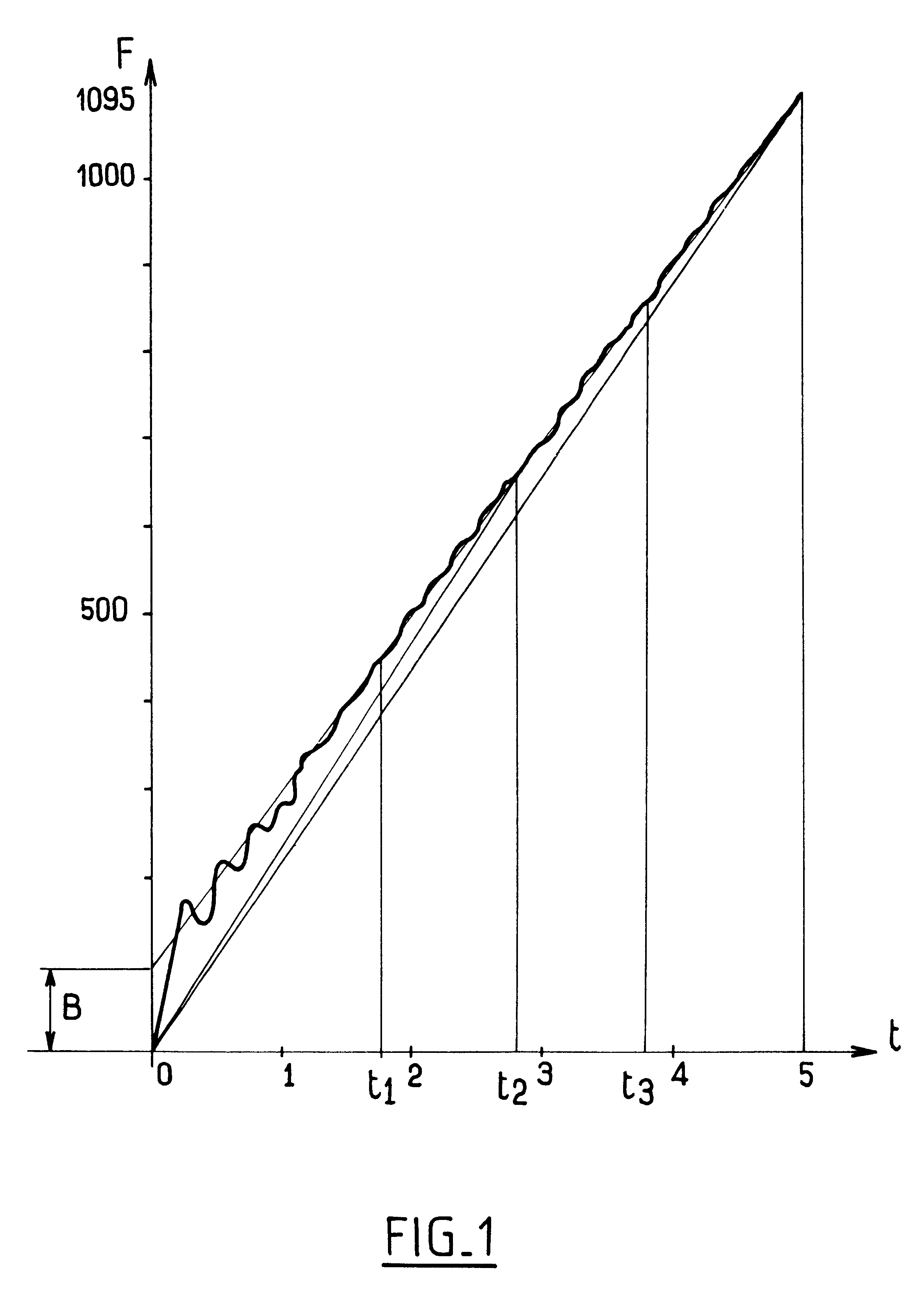
Thus, the step of calculating a mean flow rate for the substance minimizes the consequence of the oscillations on starting so that an accurate result is obtained without it being necessary to use complex calculation algorithms.

Problems solved by technology

In theory, that method should be highly satisfactory, but in practice servo-controlling the flow rate on the reference flow rate does not enable a real flow rate to be obtained that is exactly equal to the reference flow rate, so it is still necessary to perform compensation by checking the real net weight after filling and modifying the parameters of the servo-control loop for subsequent filling cycles so that the real net weight comes as close to possible to the desired net weight.
Nevertheless, while the receptacle is being put onto the weighing member and while the jet of substance is establishing itself once the flow has been turned on, the weighing member is subjected to oscillations which falsify the measured instantaneous flow rate and consequently falsify the calculated total weight of substance contained in the receptacle.
To mitigate that drawback, it is necessary to filter the signal from the weighing member, at least during the initial stages of filling, by using complex algorithms that significantly increase the cost of implementing that filling method.

Method used


Image

  • Method of filling a receptacle
  • Method of filling a receptacle
  • Method of filling a receptacle

Examples


Embodiment Construction

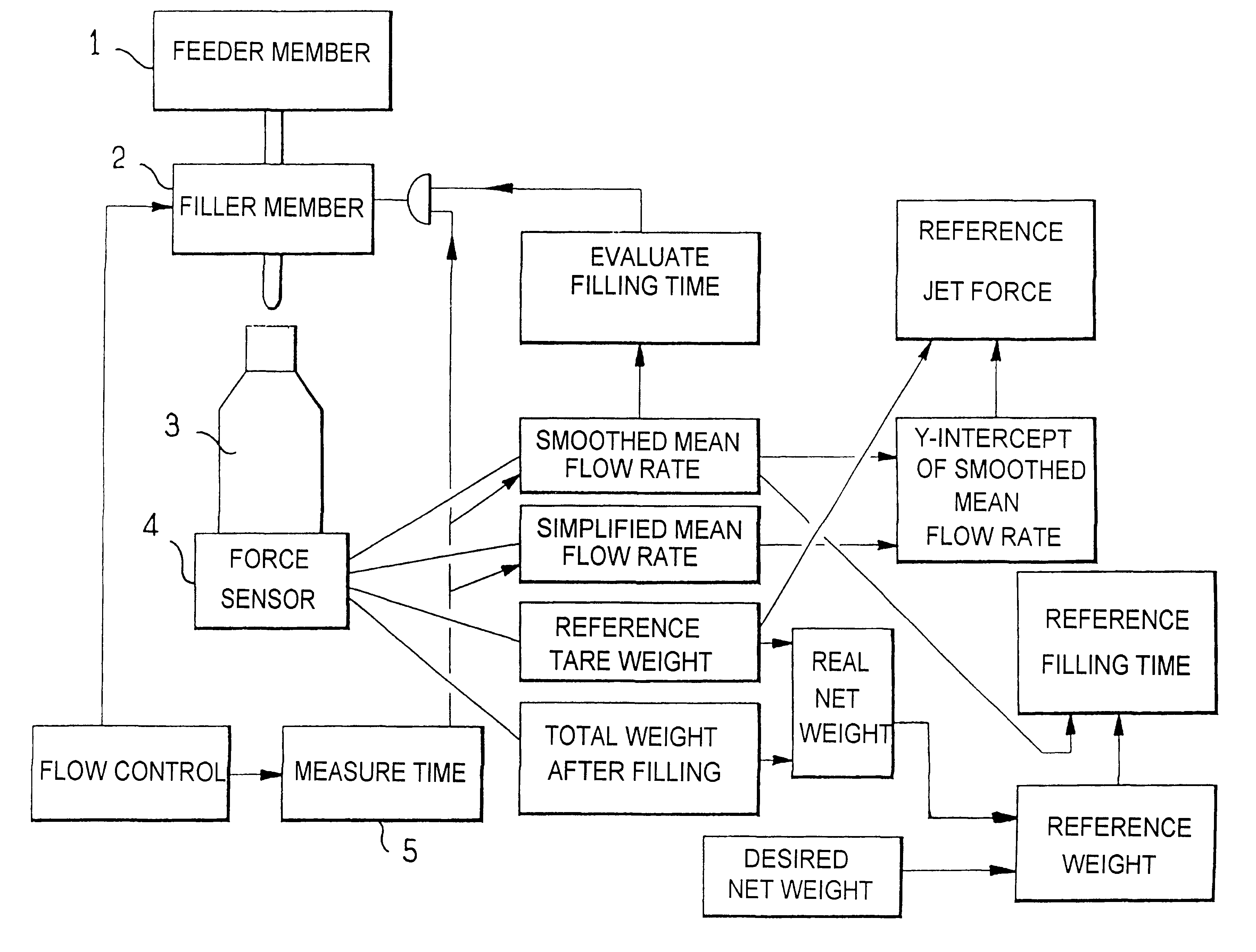
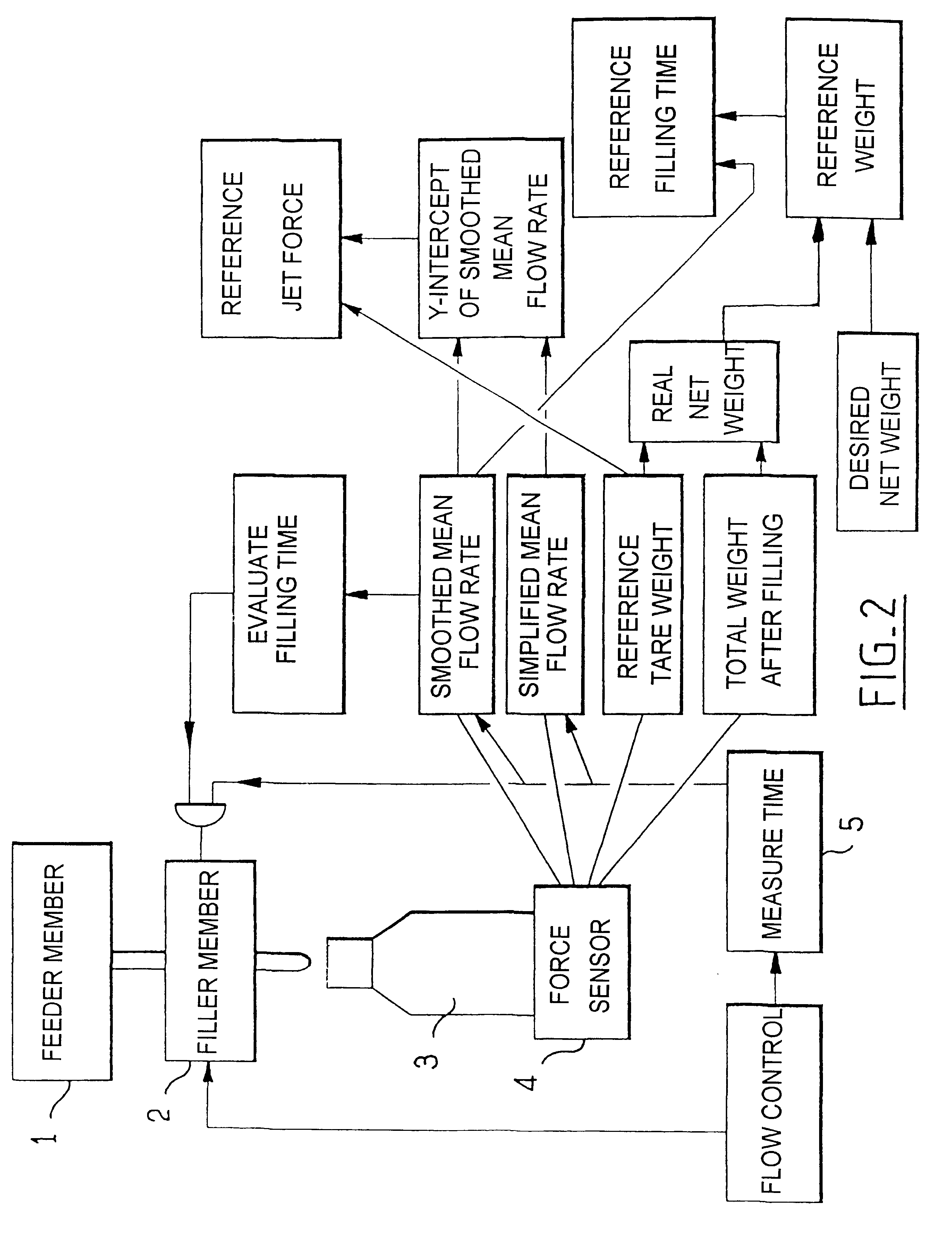
With reference to FIG. 2, the method of the invention is implemented by apparatus comprising in conventional manner a feeder member 1 connected to a filler member 2 disposed above a receptacle 3 itself carried by a force sensor 4. The feeder member is, for example, a vessel carried by the rotary platform of a carousel or a vessel separated from the carousel and connected to the platform by a pipe including a rotary joint. The flow from the feeder member can be enhanced by a centrifugal pump. By way of example, the filler member 2 is a valve or an Archimedes' screw under the control of a stepper motor, the speed of the motor determining the flow rate driven by the Archimedes' screw, particularly when the substance is a semiliquid such as mayonnaise, or is a non-uniform substance such as a sauce with lumps in it. It will be observed in this context that the filter member cannot be controlled directly on a flow rate value, but must be controlled on some other physical parameter (outlet...


PUM

PropertyMeasurementUnit
Weightaaaaaaaaaa
Timeaaaaaaaaaa
Forceaaaaaaaaaa

Abstract

A method of filling a receptacle with a net weight substance by means of a filler member disposed to introduce the substance into the receptacle while the receptacle is being carried by a force sensor, the method comprising at least one cycle comprising the steps of:placing the receptacle on the force sensor;commanding the filler member to start a flow of the substance;repeatedly measuring the time for which the substance has been flowing since the start-of-flow command was issued;measuring a value of a signal supplied by the force sensor at least at first and second separate measurement instants;calculating a mean flow rate of the substance over the time interval between the measurement instants;making at least one computed evaluation of a filling time on the basis of the calculated mean flow rate and a reference weight; andcommanding the flow of substance to stop when the flow time of the substance is equal to the evaluated filling time.

Description

The present invention relates to a method of filling a receptacle with a net weight of substance by means of a filler member disposed to introduce the substance into the receptacle while the receptacle is being carried by a force sensor.Various methods are known for filling a receptacle with a net weight of substance. Traditionally, the simplest method consists in placing a receptacle on a weighing member, the receptacle itself being disposed beneath a filler member which can be turned on and off under the control of the weighing member as a function of the apparent weight that is measured thereby. The apparent weight comprises not only the empty or "tare" weight of the receptacle plus the net weight of the substance contained in the receptacle, but also the force that results from the jet of substance on the surface of the substance contained in the receptacle. This force varies not only as a function of how wide the filler member is open, but also as a function of the viscosity of...

Claims


Application Information

Patent Timeline
IPC IPC(8): B67C3/20B67C3/02G01G13/00G01G13/285B65B3/26G01G13/08B65B57/10G01G13/12G01G13/14
CPCG01G13/2851B67C3/202
Inventor GRAFFIN, ANDRE
Owner SERAC GROUP
Learn More