
Image processing device and method employing motion detection to generate improved quality image from low resolution image

a motion detection and image processing technology, applied in the direction of instruments, television systems, standards conversion, etc., can solve the problems of aliasing distortion theorem is not satisfied, and the prefilter is not typically provided in the vertical direction, so as to reduce or eliminate the effect of aliasing distortion

Inactive Publication Date: 2001-12-11
SONY CORP
View PDF11 Cites 72 Cited by
  • Summary
  • Abstract
  • Description
  • Claims
  • Application Information

AI Technical Summary

Benefits of technology

It is, therefore, an object of the invention to provide a way to convert an undersampled image signal into an output image signal with aliasing distortion reduced or eliminated.
It is yet another object of the invention to improve the quality of a displayable image generated from a low quality input image signal.

Problems solved by technology

To correct for aliasing distortion, prefilters have been used to compensate for undersampling in the horizontal (scanning line) direction; however, such prefilters are not typically provided in the vertical direction.
As such, aliasing distortion in the vertical direction is a common problem.
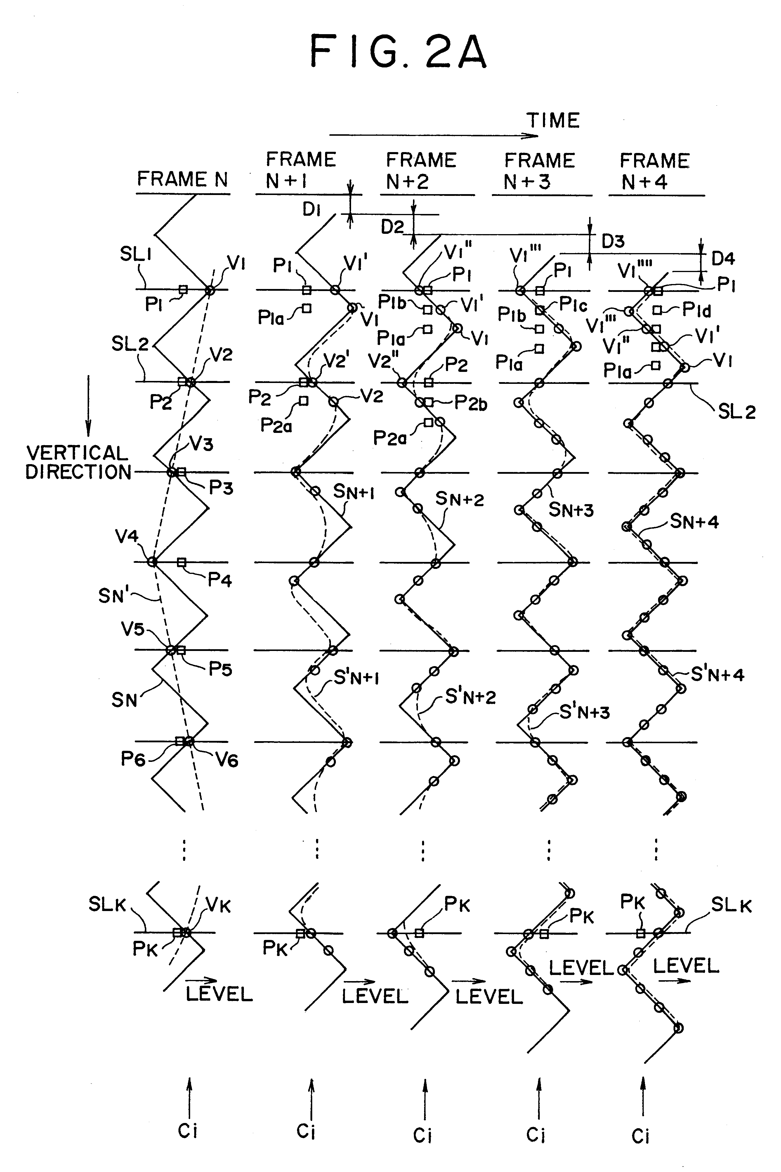
Now, if the highest spatial frequency component of the original image in the vertical direction has a period of less than twice the horizontal spacing between pixels, then the sampling theorem is not satisfied and aliasing distortion results.
With the aliasing distortion, the high frequency component of the original signal will be lost during reproduction, even if a filter to remove aliasing is employed in the vertical direction.
Such aliasing distortion may be a cause of degradation in signal processing such as Y / C separation, noise removal, quality improvement, and so forth.
If a frame with aliasing distortion changes significantly from frame to frame, as is the case in FIG. 26, then an unnatural moving image or blurring results from the perspective of the user.

Method used


Image

  • Image processing device and method employing motion detection to generate improved quality image from low resolution image
  • Image processing device and method employing motion detection to generate improved quality image from low resolution image
  • Image processing device and method employing motion detection to generate improved quality image from low resolution image

Examples


Embodiment Construction

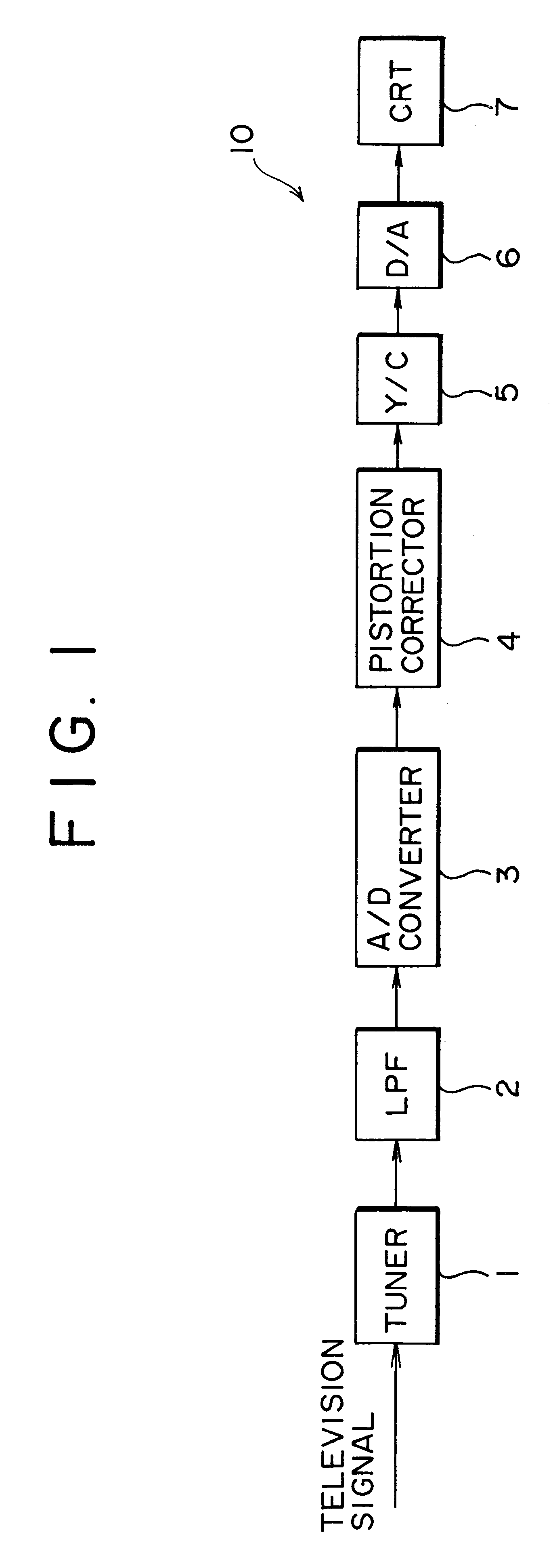
Referring to FIG. 1, a simplified block diagram of a television receiver 10 in accordance with the present invention is shown. Receiver 10 converts an input television signal to a digital signal, corrects the digital signal for aliasing distortion while enhancing its resolution, and then converts the distortion-corrected digital signal back to an analog signal for display.

Receiver 10 includes a tuner 1 for demodulating an input television broadcast signal of a selected band, which is received via an antenna or transmission line. The demodulated signal is applied to low pass filter (LPF) 2, which operates as an aliasing distortion prefilter to filter out high frequency components of the television signal. The filtered output signal of LPF 2 is applied to analog to digital (A / D) converter 3 where it is sampled and digitized. The digitized signal is then provided to distortion corrector 4 which reduces or essentially eliminates aliasing distortion in the vertical direction of the digit...


PUM


Abstract

An image signal converting apparatus for converting a first image signal into a second image signal, where the first and second image signals include a plurality of pictures of different frames. A motion detector is operable to detect motion of the first image signal between a first frame and a second frame, and processing circuitry produces the second image signal based on an assumption of a pixel at a position corresponding to the detected motion. The apparatus may be employed to produce an output signal of either the same resolution as the first image signal with aliasing distortion reduced or eliminated, or with higher resolution in vertical and / or horizontal directions.

Description

The present invention relates generally to image processing, and in particular, to an image processing device and method for reducing aliasing distortion due to undersampling of an image. The invention also relates to a technique for generating a high resolution image by increasing the number of pixels of a low resolution image.With modern digital imaging techniques, analog video signals are sampled and stored as digital data for subsequent reproduction on a cathode ray tube (CRT) or other display. It is a design goal to display such images with as high a resolution and as little distortion as possible.Images displayed on a CRT, such as images derived from television signals, video tape recorders (VTRs) or from digital versatile disc (DVD) players, are generated by repetitive scanning of electron beams in the horizontal direction. As illustrated in FIG. 25., each horizontal scan is performed from left to right, and after each scan, the beams are swept back to the extreme left and re...

Claims


Application Information

Patent Timeline
Patent Type & Authority Patents(United States)
IPC IPC(8): G06T3/40H04N7/01H04N5/14H04N5/44
CPCG06T3/4023H04N7/0125H04N7/014H04N5/147H04N5/44
Inventor KONDO, TETSUJIROWATANABE, TSUTOMUOHTSUKI, TOMOYUKI
Owner SONY CORP
Learn More